

What Is a Band Stop Filter?
A band stop filter is an electronic filter designed to reject or attenuate a specific range of frequencies while allowing frequencies outside that range to pass through. It is also known as a band-reject filter, band-elimination filter, or band-stop filter.
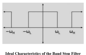



A band stop filter can be designed using different circuit configurations. One common approach combines a low-pass filter and a high-pass filter in parallel. The filter has two cut-off frequencies: a lower cut-off frequency (fL) and an upper cut-off frequency (fH).
The filter rejects frequencies between these two cut-off frequencies. It allows frequencies below the lower cut-off frequency and above the upper cut-off frequency to pass through. Therefore, it has two passbands and one stopband. The cut-off frequencies depend on the values of the components used in the circuit design.
Ideal Characteristics of a Band Stop Filter
The ideal frequency response of a band stop filter shows that frequencies within a particular range are completely rejected, while frequencies outside that range pass without attenuation. The two important cut-off frequencies are:
- fL (Lower Cut-off Frequency): The lower frequency limit of the stopband.
- fH (Upper Cut-off Frequency): The upper frequency limit of the stopband.
The main characteristics of a band stop filter are:
- It has two cut-off frequencies.
- It contains two passbands and one stopband.
- It rejects a specific range of frequencies.
- It allows frequencies below fL and above fH to pass.
- Its frequency response is opposite to that of a band-pass filter.
Band Stop Filter Theory
The working principle of a band stop filter is based on the combination of low-pass and high-pass filtering operations.

When an input signal is applied to the circuit:
- The low-pass filter allows low-frequency signals to pass through.
- The high-pass filter allows high-frequency signals to pass through.
- When their outputs are combined appropriately, frequencies within the selected stopband are attenuated.
As a result, the circuit allows low and high frequencies to pass while rejecting the frequencies in between.
Frequency Response of a Band Stop Filter
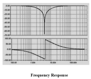
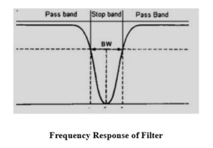
The frequency response represents how the output of a band stop filter changes with respect to the input frequency. In a typical band stop filter, low-frequency and high-frequency signals pass through the circuit, while signals within the stopband are attenuated. In practical circuits, the transition between the passband and stopband is not perfectly sharp. The amount of attenuation and the shape of the frequency response depend on the circuit design and the components used.
Band Stop Filter Using R, L and C
A band stop filter can also be designed using passive components such as a resistor (R), inductor (L), and capacitor (C). These components are connected in a suitable arrangement to reject a particular range of frequencies.
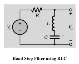

The behaviour of an inductor and capacitor changes with the input frequency:
- At low frequencies: An inductor offers low reactance, while a capacitor offers high reactance.
- At high frequencies: An inductor offers high reactance, while a capacitor offers low reactance.
- At the resonant frequency: The inductor and capacitor can produce a strong frequency-selective response, depending on their series or parallel connection.
By selecting suitable component values and circuit connections, a band stop response can be obtained. The resistor helps control damping and the quality factor of the filter.
Working of an RLC Band Stop Filter
In an RLC band stop filter, the resistor, inductor, and capacitor are arranged to attenuate signals within a selected frequency range. At the resonant frequency, the circuit produces a strong rejection of the unwanted signal. Frequencies outside the rejection range are allowed to pass with comparatively less attenuation. The lower and upper cut-off frequencies depend on the values of the resistor, inductor, and capacitor, as well as the circuit configuration.
Notch Filter
A notch filter is a special type of band stop filter designed to reject a very narrow range of frequencies, usually around a particular Centre frequency. It is commonly used to eliminate unwanted interference at a specific frequency.

One commonly used notch filter is the Twin-T notch filter. It consists of two T-shaped networks connected in parallel: one resistive-capacitive network and one resistive network with a capacitor arrangement. For a balanced Twin-T notch filter, the centre frequency is given by:
fC = 1 / (2πRC)
Where:
- fC: Centre or notch frequency in hertz (Hz).
- R: Resistance in ohms (Ω).
- C: Capacitance in farads (F).
The resistor and capacitor values are selected according to the required notch frequency and circuit configuration. Notch filters are particularly useful for removing power-line interference at 50 Hz or 60 Hz in audio and electronic equipment.
Frequency Response of a Notch Filter
The frequency response of a notch filter shows a deep attenuation point at its centre frequency. Frequencies around this point are strongly reduced, while frequencies outside the narrow stopband are allowed to pass.
Applications of Band Stop Filters
Band stop filters are widely used in electronic, communication, audio, and signal-processing systems. Some important applications are discussed below.
1. Audio Systems
Band stop filters are used in electric guitar amplifiers, audio equipment, and public address (PA) systems to reduce unwanted noise and electrical hum. They can help eliminate interference at specific frequencies, such as 50 Hz or 60 Hz.
2. Image and Signal Processing
These filters are used in image and signal processing applications to reduce unwanted frequency components and periodic noise from signals and images.
3. Radio Communication
Band stop filters are used in radio receivers and communication systems to reduce unwanted interference and noise within a specific frequency range.
4. Medical Equipment
In biomedical instruments, notch filters are used to remove power-line interference from signals such as electrocardiogram (ECG) recordings. This helps improve the quality of the measured signals.
5. DSL Communication Systems
Band stop filters can be used in communication systems, including DSL applications, to reduce unwanted interference between different frequency bands.
6. Harmonic and Noise Reduction
Unwanted noise and harmonics can distort communication signals and cause errors during data transmission. Band stop filters help reduce selected unwanted frequency components and improve signal quality.
7. Public Address (PA) Systems
These filters are used in audio amplification systems to reduce unwanted frequencies, feedback, and electrical interference, helping improve sound quality.
8. Optical Communication and Spectroscopy
Frequency-selective filtering techniques are used in optical communication and spectroscopy to remove unwanted spectral components. For example, optical notch filters are used in Raman spectroscopy to suppress intense laser light and make weaker Raman signals easier to detect.
Conclusion
A band stop filter is an important electronic filter used to eliminate or attenuate unwanted frequencies within a specific range. It allows frequencies below and above the stopband to pass through. Different circuit configurations, including RLC and Twin-T notch filters, are used to achieve the required filtering characteristics. Band stop filters are widely used in audio systems, communication equipment, medical instruments, image processing, and other electronic applications to reduce unwanted noise and interference.