

Introduction
The 24GHz Millimeter-Wave (mmWave) Radar Sensor is an advanced human static presence detection module designed for security, safety, and smart automation applications. Detecting human presence in an Area of Interest (AOI) is essential in environments such as homes, offices, hotels, and high-security areas.
Among various detection technologies, radar technology is one of the most reliable and efficient methods for detecting human presence. Radar systems use radio waves to detect objects and determine their position, speed, and angle. A radar system consists of a transmitter that emits electromagnetic (microwave) waves. These waves reflect off objects and return to the receiver, helping determine the object’s location and movement.
In addition to motion detection, modern mmWave radar technology can even detect subtle human biological signatures such as breathing patterns and heartbeats.

Advantages Over Traditional PIR Sensors
Compared to traditional PIR (Passive Infrared) sensors, the Human Static Presence Module offers significantly higher sensitivity. It can detect:
- Standing individuals
- Moving persons
- Falling movements
- Micro-movements such as breathing
Because it operates using millimeter-wave transmission, it continues functioning even when partially obstructed by materials such as plastic or thin barriers. Unlike PIR sensors, which respond only to motion and may stop detecting when movement ceases, this module continuously monitors human presence.
This makes it highly suitable for applications in living rooms, hotel rooms, offices, healthcare facilities, and correctional institutions.
What is an mmWave Radar Sensor?
mmWave (millimeter-wave) radar sensors operate within the frequency range of 30GHz to 300GHz. Due to their extremely short wavelengths, they provide:
- Sub-millimeter accuracy
- High-resolution detection
- Small antenna size
- Penetration through materials such as plastic, drywall, and clothing
- Reliable operation in rain, fog, dust, and snow
The 24GHz radar module uses FMCW (Frequency Modulated Continuous Wave) and CW signals. The working process includes:
- The sensor transmits FMCW and CW radio waves into the detection area.
- These waves reflect off moving, micro-moving, or stationary targets.
- The internal MMIC circuit converts reflected waves into electrical signals.
- Data processing algorithms analyze the signals to determine human presence and activity.
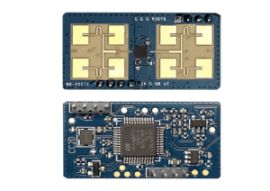
24GHz Radar Module Overview
This radar module is designed for microcontroller-based applications. It operates with low power consumption and offers wide detection coverage.
- Operating Voltage: 3.3V – 5V
- Current Consumption: 80–90mA
- Maximum Detection Range: Up to 9 meters
- Wide Beam Angle Coverage
Interface (2.0 mm, 4-Pin)

- VCC – 5V Power Supply
- GND – Ground Connection
- URX – TTL Serial Receive
- UTX – TTL Serial Transmit
Technical Specifications
- Frequency: 23.5GHz – 24.5GHz
- Modulation Method: FMCW
- Detection Distance: >4m (static), >8m (moving)
- Installation Height: 3m (static detection radius >2m)
- Power Supply: 3.3V – 5V
- Current: 80mA
- Output Serial Level: 3.3V
- Detection Cycle: Adaptive
- Antenna Half-Power Angle: Horizontal ±22°, Vertical ±24°
- Data Format: Serial Port ASCII Output
Key Features
- Reliable Technology: Infineon mmWave FMCW industrial radar technology
- Doppler Radar Principle: Uses Near Distance Sensor (NDS) technology operating at 24GHz
- Intelligent Algorithm: Distinguishes between occupied and unoccupied conditions automatically
- Privacy Protection: Provides detection without capturing personal identity
- Flexible Installation: Works properly even with partial obstructions
- Safe Operation: Outputs harmless 10 dBm energy power
- High Accuracy: More than 95% detection accuracy with reduced interference
- High Robustness: Functions effectively under varying temperature, humidity, dust, airflow, and lighting conditions
- High-Performance Antenna: Detects micromotions with Horizontal 90° / Vertical 60° coverage
Measurement Distance
- Motion Detection: Up to 12 meters
- Micromotion Detection: Up to 5 meters
- Body Presence Detection: Up to 3 meters
Response Time
- Unoccupied to Occupied: Within 0.5 seconds
- Occupied to Unoccupied: Above 1 minute
Customizable Radar Module
The radar module supports secondary development, allowing customization of radar parameters, communication protocols, antenna configuration, and functional features. This makes it suitable for smart home systems, IoT devices, security monitoring, healthcare monitoring, and industrial automation applications.