

Introduction
Measuring instruments and test equipment are extremely useful for measuring physical quantities. These instruments are widely used in engineering, quality control, research laboratories, and physical sciences. Various types of measuring tools are available in the market, such as accelerometers, Q meters, LCR meters, RLC meters, and many others. These instruments may be electronic, electrical, or mechanical in nature.
What is an LCR Meter?
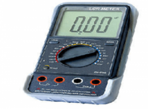

An LCR meter is a measuring instrument used to measure the inductance (L), capacitance (C), and resistance (R) of electronic components, sensors, and circuits. In addition to L, C, and R, an LCR meter can also measure parameters such as quality factor (Q), dissipation factor (D), voltage, current, conductance, phase angle, and susceptance. The parameters L, C, and R play a major role in determining the performance of electronic components. IET Labs is one of the leading manufacturers of LCR meters and produces a wide range of instruments for measuring both low and high values of resistance and capacitance.

Features of LCR Meter
- Measurement accuracy up to 0.1%
- LCD display with white backlight
- Battery life up to 24 hours
- Low power consumption
- Automatic component identification
- Operates using a 9 V battery
- Constant output electrical impedance of 100 ohms
- Auto power-off feature
LCR Meter Block Diagram
The block diagram of an LCR meter mainly consists of two important sections:
- Wheatstone Bridge
- RC Ratio Arm Circuit

By connecting a component to the appropriate bridge, its value can be measured easily. The Wheatstone bridge is mainly used for resistance measurement, while the RC ratio arm circuit is used for measuring inductance and capacitance. In an LCR meter, DC quantities are measured by exciting the bridge with DC voltage. For AC measurements, the Wheatstone bridge is excited using an AC signal. An internal oscillator generates an AC excitation signal, typically at a frequency of 1 kHz.
LCR Meter Working Principle
The working principle of an LCR meter is based on the bridge balance method. By adjusting the controls, the bridge can be balanced to the null position, allowing accurate measurement of the component value.
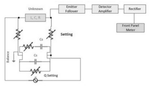
The main functional blocks involved in the working of an LCR meter include:
- Emitter follower
- Detector amplifier
- Rectifier
- Front panel meter
The output from the bridge circuit is first applied to the emitter follower. The output of the emitter follower is then fed to the detector amplifier. The detector amplifier is necessary because the measuring signal may be very small, and without amplification, the meter indication would not be visible. During signal processing, attenuation reduces the signal strength. Therefore, amplification is required to obtain a usable signal. The amplified AC signal is then converted into a DC signal using a rectifier.
Once the bridge is excited with an AC signal, the AC output is converted into a DC signal, which is displayed on the front panel meter. The component to be measured can be connected to the test terminals, and measurement depends on the selected function.
Front Panel Controls of LCR Meter
ON / OFF Switch
The ON/OFF switch is used to power the LCR meter. When the switch is turned ON, the meter receives the power supply, and an indicator on the front panel shows that the instrument is operational.
Test Terminals
The test terminals are provided on the front panel. The component to be measured is connected directly to these terminals.
Function Selector
The function selector is used to select the type of measurement, such as resistance (R), inductance (L), or capacitance (C).
Range Selector
The range selector allows the user to choose the appropriate measurement range for low or high value components. Proper selection of range is essential for accurate measurement.
Scale
The measured value is displayed on the calibrated scale of the LCR meter. The pointer or digital display indicates the final reading.
Advantages of LCR Meter
- Handheld LCR meters are lightweight, portable, and battery-operated
- Benchtop LCR meters provide higher accuracy and advanced features
- Customizable test frequencies are available in advanced models
- Computer control and data logging capabilities
- No external voltage issues during measurement
- Reliable performance and long service life
- High precision and accuracy
- User-friendly and compatible with various applications
Disadvantages of LCR Meter
- Measures only passive components
- LCD performance depends on battery condition
- Limited voltage handling capacity
- Excess supply voltage may damage the instrument
Applications of LCR Meter
- Measurement of resistance, inductance, and capacitance of electronic components
- Testing of circuits at different frequencies
- Impedance (Z) measurement
- Quality control and component testing
- Used by electrical and electronics engineers
- Manufacturing and research laboratories