

What is a Logic Analyzer?
A logic analyzer is a test instrument used to analyze and troubleshoot complex digital or logic circuits. It is especially useful for engineers and developers who need to understand the timing relationships and logic states of multiple digital signals.

While oscilloscopes can perform some similar functions, logic analyzers are designed to display the relative timing of a large number of digital signals simultaneously. This allows engineers to observe how different logic lines interact within a digital system. In essence, a logic analyzer captures and displays logic signals so that the operation of several digital lines can be monitored and analyzed together. Many modern oscilloscopes combine logic analyzer features and are known as mixed signal oscilloscopes.

Logic analyzers are available in various formats. Traditional standalone instruments still exist, but many modern logic analyzers are computer-based, offering greater flexibility, processing power, and advanced analysis capabilities.
Logic Analyzer Development
Logic analyzers were originally developed to debug and troubleshoot microprocessor-based systems. When microprocessors became widely used in the early 1980s, engineers needed tools that could monitor many digital lines simultaneously.
Conventional oscilloscopes were unable to provide this level of functionality. As a result, logic analyzers were developed to meet the growing complexity of digital circuits. Over time, logic analyzers evolved alongside digital systems. The number of channels increased, operating speeds improved, and advanced triggering and decoding capabilities were introduced.
Logic Analyzer Characteristics
Multiple Channels
Logic analyzers are designed to monitor a large number of digital signals at the same time. Typical instruments support between 32 and 200 or more channels, with each channel monitoring one digital line. Some high-end or specialized logic analyzers support significantly higher channel counts, allowing analysis of highly complex systems.
Logic State Timing Display
Logic analyzers display digital signals using a horizontal time axis and a vertical logic state axis. This produces a clear timing diagram showing when each signal is high or low.
Displays Logic States Only
The analyzer converts incoming signals into logic high or logic low states for internal processing. It displays timing relationships rather than voltage levels.
No Analog Signal Display
Unlike oscilloscopes, logic analyzers do not display analog waveforms. They are strictly intended for digital signal analysis. If analog behavior must be observed, an oscilloscope is required.
Logic Analyzer vs Oscilloscope
| Logic Analyzer | Oscilloscope |
|---|---|
| Used for debugging and verifying digital logic operations | Used for measuring analog waveforms |
| Displays logic states and timing relationships | Displays voltage amplitude and waveform shape |
| Correlates many digital signals simultaneously | Limited number of channels |
| Detects timing violations and protocol errors | Detects waveform distortion, noise, and ringing |
| Useful for tracing embedded software behavior | Useful for measuring rise time, jitter, and transients |
Types of Logic Analyzers
Modular Logic Analyzers
Modular logic analyzers are high-end instruments that consist of a chassis and multiple plug-in modules. Channel count can be increased by adding additional modules. These analyzers offer the highest performance and flexibility but are also the most expensive.
Portable Logic Analyzers
Portable logic analyzers integrate all components into a single compact unit. They are suitable for field service, educational use, or applications with limited budgets.
PC-Based Logic Analyzers
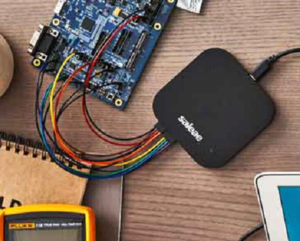
PC-based logic analyzers are becoming increasingly popular. They consist of a hardware capture device connected to a computer via USB or Ethernet. The computer provides processing power and display capabilities, reducing system cost while maintaining high performance. USB logic analyzers are especially popular among hobbyists and developers.
Logic Analyzer Applications
Logic analyzers are primarily used to examine and debug digital signals. They were especially useful when digital systems consisted of many separate integrated circuits with accessible test points. Modern systems often use highly integrated System-on-Chip (SoC) designs, making direct access to internal signals difficult. Despite this, logic analyzers remain valuable tools.
Logic analyzers are widely used with development platforms such as Arduino, Raspberry Pi, and other embedded systems. They can time-correlate multiple buses such as UART, SPI, and I2C on a single display. For example, data flow from a microcontroller to EEPROM and then to another peripheral can be observed clearly. Such multi-signal correlation is difficult or impossible using a standard oscilloscope.
Conclusion
Logic analyzers are powerful test instruments that provide deep insight into the operation of digital circuits. By displaying logic states and timing relationships across many channels, they allow engineers to diagnose problems that other instruments cannot easily detect. From low-cost USB logic analyzers for hobbyists to advanced professional systems, logic analyzers continue to play a vital role in digital electronics design and debugging.