

Introduction
A power analyzer is an instrument used to monitor and analyze the quality of electrical power. Electric power is defined as the rate at which electrical energy is transferred in a circuit and is measured in watts (joules per second).
Electricity used in homes and industries is generated by power generators and distributed through the electrical power grid. Poor power quality can damage equipment or cause malfunction. Therefore, continuous monitoring of power quality is essential to ensure safe and reliable operation of electrical systems.
What is a Power Analyzer?
A power analyzer, also known as a power quality analyzer, is a device used to measure and evaluate the quality of electrical power supplied to a load. Power quality refers to the compatibility between the power source and the connected load, ensuring that the load operates correctly without damage.

Poor power quality can occur due to voltage fluctuations, frequency variations, harmonics, transient currents, and interruptions. A power analyzer helps detect, measure, and diagnose these issues. Good power quality is characterized by a stable voltage within specified limits, a steady AC frequency close to its rated value, and a smooth waveform.
Circuit Diagram of Power Analyzer
A typical power analyzer consists of two isolated input channels for voltage and current measurement. The voltage input includes an attenuator, while the current input uses a built-in current shunt.
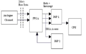

A high-speed Digital Signal Processor (DSP) processes the sampled voltage and current signals. An FPGA unit coordinates internal operations, and a separate CPU manages data display, storage, and wireless communication.
Power Analyzer Connection
Electrical power flows from generators through transmission lines, distribution networks, and finally reaches consumers via energy meters. Power analyzers are installed at key points to monitor power quality effectively.
- Main Switchboards: High-precision power analyzers monitor overall power quality and detect anomalies.
- Distribution Switchboards: These analyzers track electrical parameters and raise alarms if irregularities occur.
- Secondary Switchboards: Used to monitor individual loads and log detailed power consumption data.
Current measurements can be performed using current transformer clamps without opening the circuit, making installation safer and more convenient.
Power Analyzer Working Principle
Power analyzers with clamp-type sensors are commonly used for maintenance and inspection purposes. A three-phase power analyzer uses three clamps to measure all phases simultaneously. Modern power analyzers are portable and support wireless data transmission. Each measurement channel includes an attenuator for voltage and a shunt for current measurement, followed by buffering, gain stages, and an analog-to-digital converter.
The DSP controls gain and conversion processes and ensures high accuracy. Digital calibration eliminates the need for manual adjustments. A power analyzer can measure parameters such as real power (W), apparent power (VA), reactive power (VAr), power factor, phase angle, true RMS values, harmonics, impedance, voltage surges, and transients. Measurement results can be accessed and controlled through serial, LAN, or GPIB interfaces.
Advanced Power Analyzer
Advanced power analyzers provide additional measurements beyond electrical power. They are used in industrial applications to evaluate mechanical parameters such as torque and speed. These analyzers support advanced calculations including:
- Efficiency mapping
- Fast Fourier Transform (FFT)
- Harmonic analysis
- Fundamental power
- RMS measurements
- DQ current and space vector analysis
- Polar diagrams and symmetrical components
Power Analyzer Measurements
Depending on the model, a power analyzer can measure voltage, current, power, peak values, RMS values, harmonics, phase angle, and frequency. Most modern analyzers include onboard data logging and storage. Data can be viewed later or transferred to external systems via USB or Ethernet for further analysis.
Applications of Power Analyzer
- Identifying electrical faults and disturbances
- Monitoring energy consumption and cost analysis
- Improving energy efficiency through real-time monitoring
- Reducing unnecessary power usage
- Analyzing variable-speed motor drives
- Measuring efficiency and power quality of LED drivers
- Standby power analysis using software tools
- Monitoring transformers, generators, substations, and power distribution networks
Power analyzers play a crucial role in maintaining reliable electrical systems by enabling accurate measurement, logging, and analysis of power quality parameters.