

Introduction
To create more complex resistor networks, individual resistors can be connected together in series, in parallel, or in a combination of both. When resistors are connected in series, their individual resistance values combine mathematically to form a single equivalent resistance

.A resistor is a fundamental electronic component used to convert voltage into current or current into voltage. By properly selecting resistance values, different weightings can be applied to the resulting voltage or current, allowing resistors to be used in voltage reference circuits and signal-conditioning applications.

Regardless of the complexity of the resistor network, all resistors obey the same fundamental principles described by Ohm’s Law and Kirchhoff’s Circuit Laws. Any series or complex resistor network can be replaced by a single equivalent resistance (REQ) or impedance (ZEQ).
What Are Resistors in Series?
When resistors are connected end-to-end in a single continuous path, they are said to be connected in series. In a series connection, there is only one path for current to flow.
Because there is no alternative path, the same current flows through each resistor in the series chain. The current passing through the first resistor must also pass through the second, third, and all subsequent resistors.
Therefore, at any point in a series resistor network, the magnitude of current remains constant throughout the circuit.
![]()

Series Resistor Circuit Characteristics
- The same current flows through all resistors
- Total resistance increases as more resistors are added
- The applied voltage is divided across the resistors
Equivalent Resistance of Resistors in Series


Since each resistor in a series circuit carries the same current, the total or equivalent resistance of the circuit is equal to the sum of the individual resistance values.
Formula:
RT = R1 + R2 + R3 + … + Rn
Example:
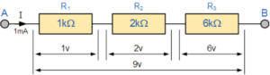
R1 = 1kΩ, R2 = 2kΩ, R3 = 6kΩ
REQ = 1kΩ + 2kΩ + 6kΩ = 9kΩ
Thus, the three resistors connected in series can be replaced by a single 9kΩ resistor.
Voltage Distribution in Series Resistors
In a series circuit, the total supply voltage is divided across the individual resistors. Each resistor drops a portion of the total voltage proportional to its resistance value.
This principle is widely used in voltage divider circuits.
Applications of Resistors in Series
- Voltage Divider Circuits: Series resistors are commonly used to generate different voltage levels from a single supply voltage.
- Sensor Circuits: One resistor in a voltage divider can be replaced with a sensor such as a thermistor, light-dependent resistor (LDR), or switch to convert a physical quantity into an electrical signal.
- Temperature Measurement: For example, a thermistor may have a resistance of 10kΩ at 25°C and 100Ω at 100°C. The resulting output voltage changes with temperature and can be measured.
- Current Limiting: Series resistors are used to limit current flow in LEDs and protection circuits.
Conclusion
Resistors in series provide a simple and effective way to increase resistance, divide voltage, and control current in electrical and electronic circuits. By understanding their behavior and equivalent resistance calculation, designers can easily analyze and simplify complex resistor networks.