

What is a Sallen-Key Filter?
The Sallen-Key filter is one of the simplest active two-pole filter circuits. It is commonly used to design low-pass and high-pass filters using two resistors, two capacitors, and an operational amplifier (op-amp). The Sallen-Key circuit is a simplified version of the Voltage-Controlled Voltage Source (VCVS) filter. It was first described by R. P. Sallen and E. L. Key of the Massachusetts Institute of Technology (MIT) in 1955.
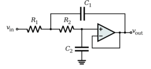



It is important to understand that Sallen-Key is a filter topology, not a filter response characteristic. Butterworth, Bessel, and Chebyshev describe different filter characteristics, while Sallen-Key describes a circuit arrangement that can be used to implement these characteristics by selecting suitable component values. Sallen-Key filters are mainly used in low-pass and high-pass configurations. They can also be used to create band-pass responses with additional circuit arrangements.

Working Principle of a Sallen-Key Filter
A Sallen-Key filter uses an op-amp along with resistors and capacitors to control the frequency response of an input signal. The op-amp is commonly connected as a voltage follower or buffer, although non-inverting gain configurations are also possible. The circuit consists of two RC sections connected in a specific arrangement. These components determine the cutoff frequency and quality factor (Q) of the filter. Sallen-Key filters are simple to design and are useful when a second-order filter response is sufficient. Higher-order filters can be created by cascading multiple stages.
Sallen-Key Low-Pass Filter
A Sallen-Key low-pass filter allows low-frequency signals to pass while attenuating high-frequency signals above the cutoff frequency. It uses two resistors, two capacitors, and an operational amplifier. The op-amp is generally connected as a buffer to provide the required active filter operation. The cutoff frequency and quality factor of a low-pass Sallen-Key filter depend on the resistor and capacitor values. For a unity-gain Sallen-Key low-pass circuit, the standard equations are:
Cutoff Frequency:
fc = 1 / (2π√(R₁R₂C₁C₂))
Quality Factor:
Q = √(R₁R₂C₁C₂) / [C₂(R₁ + R₂)]
Where:
- R₁ and R₂: Resistor values.
- C₁ and C₂: Capacitor values.
- fc: Cutoff frequency in hertz.
- Q: Quality factor of the filter.
Sallen-Key High-Pass Filter
A Sallen-Key high-pass filter allows high-frequency signals to pass while attenuating low-frequency signals below the cutoff frequency. It uses the same basic active filter concept as the low-pass version. The high-pass configuration can be obtained by interchanging the positions of the resistors and capacitors in the corresponding circuit arrangement. The cutoff frequency depends on the selected resistor and capacitor values.
Simplified Sallen-Key Filter Design
The design equations can be simplified by selecting suitable relationships between the resistor and capacitor values. For example, we can define:
- R₁ = mR
- R₂ = R/m
- C₁ = nC
- C₂ = C/n
Where m and n are component scaling factors. For this arrangement, the cutoff frequency becomes:
fc = 1 / (2πRC)
For a unity-gain low-pass Sallen-Key filter, the quality factor becomes:
Q = n / (m + 1/m)
These simplified relationships make it easier to select component values during filter design.
Butterworth Filter Design Using Sallen-Key Topology
A Butterworth filter is designed to provide a maximally flat magnitude response in the passband. A second-order Butterworth filter has a quality factor of approximately 0.707. For a unity-gain Sallen-Key low-pass filter, choosing m = 1 gives:
Q = n / 2
To obtain a Butterworth response:
0.707 = n / 2
Therefore:
n ≈ 1.414
This means that C₁ should be approximately 1.414 times C₂ when both resistors have equal values.
Example: Design a 10 kHz Butterworth Sallen-Key Filter
Let us design a second-order Butterworth low-pass filter with a cutoff frequency of 10 kHz.
Given:
- Cutoff frequency = 10 kHz
- R₁ = R₂ = R
- Quality factor Q = 0.707
For equal resistors, the required capacitor ratio is approximately:
C₁ / C₂ = 1.414
Select the following standard capacitor values:
- C₁ = 20 nF
- C₂ = 14.1 nF
Using the cutoff frequency equation:
fc = 1 / (2πR√(C₁C₂))
Rearranging the equation:
R = 1 / (2πfc√(C₁C₂))
Substituting the selected values gives a resistor value of approximately 1.13 kΩ.
Therefore, we can select:
- R₁ = 1.1 kΩ
- R₂ = 1.1 kΩ
These are practical standard component values. The actual cutoff frequency and Q factor will vary slightly because of component tolerances and the selected standard values.
Performance of the Designed Circuit
The designed circuit can be evaluated using circuit simulation software or an online filter calculator. The frequency response analysis helps determine the cutoff frequency and attenuation characteristics. Transient analysis can be used to observe the circuit’s response to a step input.
The original design example reports a simulated cutoff frequency of approximately 10.23 kHz and a step-response overshoot of around 4%. Actual results depend on the precise component values, op-amp model, and circuit implementation.
Advantages of Sallen-Key Filters
- Simple circuit design and implementation.
- Requires fewer components.
- Uses commonly available resistors, capacitors, and operational amplifiers.
- Suitable for low-pass and high-pass filter applications.
- Multiple stages can be cascaded to obtain higher-order filters.
Applications of Sallen-Key Filters
Sallen-Key filters are used in many electronic and signal-processing applications, including:
- Audio Systems: Used for frequency control and audio signal filtering.
- Signal Processing: Helps remove unwanted frequency components from signals.
- Communication Systems: Used in signal conditioning and frequency selection circuits.
- Sensor Circuits: Helps reduce noise in signals received from sensors.
- Data Acquisition Systems: Used as an analog filter before analog-to-digital conversion.
- Electronic Circuits: Used in active low-pass and high-pass filter designs.
Conclusion
The Sallen-Key filter is a simple and widely used active filter topology. It uses resistors, capacitors, and an operational amplifier to implement low-pass and high-pass filters. Its simple design, low component count, and flexibility make it suitable for many electronic applications. By selecting appropriate component values, Sallen-Key circuits can also be designed to provide Butterworth, Bessel, and other desired filter responses.