

Definition
A logic probe is a simple, low-cost digital testing device used to analyze logic levels in digital electronic circuits. It is mainly used to detect logic HIGH, logic LOW, and pulsing signals in circuits that use TTL or CMOS logic.
What is a Logic Probe?
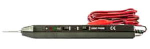
A logic probe, also known as a digital tester, is a handheld pen-like device with indicator LEDs that show the state of the signal being tested. It helps technicians and students quickly verify whether a digital signal is HIGH, LOW, or switching.


Logic probes are commonly used by hobbyists and experimenters because of their simplicity and low cost. However, they are rarely used in professional laboratories due to their limited measurement capability compared to oscilloscopes and logic analyzers.
Working of a Logic Probe
Logic probes are usually powered directly from the circuit under test. They include alligator clips to connect to the power supply and ground of the circuit. Once connected, the probe tip is touched to the test point to observe the logic state.
Most logic probes contain three indicator LEDs:
- Logic HIGH: Indicated by a red LED
- Logic LOW: Indicated by a green LED
- Pulse Detection: Indicated by an amber or yellow LED
Some advanced logic probes can also detect a tri-state condition, where the output is neither HIGH nor LOW.
Logic Probe Measurements
A logic probe is limited in functionality but can perform several basic digital measurements:
- Logic High: Detects when a signal is at a digital HIGH level
- Logic Low: Indicates a digital LOW signal
- Digital Pulses: Detects rapidly changing signals or clock pulses
- Tri-State Condition: Indicates when a line is in a floating or disabled state
Advantages of Logic Probe
- Low Cost: Much cheaper than oscilloscopes and logic analyzers
- Easy to Use: Simple connection and instant results
- Portable: Compact and handheld design
- Quick Fault Detection: Useful for basic troubleshooting
Disadvantages of Logic Probe
- Very Rough Measurement: Only shows logic states, not waveform details
- Poor Display: Uses LEDs instead of detailed visual output
- Limited Functionality: Cannot replace oscilloscopes or logic analyzers
Typical Logic Probe Specifications
The specifications of logic probes may vary, but common values are listed below:
| Parameter | Specification |
|---|---|
| Logic 1 (TTL) | > 2.3V ± 0.02V |
| Logic 1 (CMOS) | > 70% of Vcc ± 10% |
| Logic 0 (TTL) | < 0.08V ± 0.02V |
| Logic 0 (CMOS) | < 30% of Vcc ± 10% |
| Maximum Supply Voltage | 20 V |
| Power Supply Range | 5 – 15 V |
| Input Impedance | 1 MΩ |
| Maximum Input Frequency | 20 MHz |
| Minimum Detectable Pulse Width | 30 ns |
Conclusion
A logic probe is a valuable and economical diagnostic tool for basic digital circuit testing. Although it has limitations, it is extremely useful for beginners, students, and technicians when troubleshooting simple electronic systems.