

Introduction
A variable capacitor is a type of capacitor whose capacitance value can be adjusted. This capacitor consists of two conductive plates, where the effective overlapping area between the plates can be changed to vary the capacitance. Variable capacitors are mainly classified into two types: air capacitors and trimmer capacitors. These capacitors are commonly used in LC circuits for frequency tuning applications, particularly in radio receivers. This article discusses the construction, working, and applications of an air capacitor.
What is an Air Capacitor?
An air capacitor is a type of capacitor in which air acts as the dielectric medium. These capacitors may be designed with either fixed or variable capacitance. However, fixed air capacitors are rarely used today, as better alternatives are available. Variable air capacitors are widely preferred due to their simple design and reliability.


An air capacitor consists of two sets of semicircular metal plates separated by air. One set of plates is fixed, while the other is movable and connected to a rotating shaft. By rotating the shaft, the overlap between the plates changes, thereby varying the capacitance.
Maximum capacitance occurs when the overlap between the two plate sets is maximum, while minimum capacitance occurs when there is no overlap. Reduction gear mechanisms are often used to achieve fine tuning and improved accuracy.
Air capacitors typically have a capacitance range of 100 pF to 1 nF and an operating voltage range of 10 V to 1000 V. Due to the low dielectric strength of air, electrical breakdown may occur if the voltage exceeds the rated value.
Air Capacitor Construction and Working
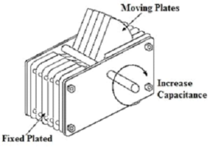

An air capacitor consists of multiple semicircular aluminum plates mounted on a central shaft. These rotating plates are placed between an equal number of fixed aluminum plates. A control shaft passes through the center of the assembly and allows rotation of the movable plates.
The plates are arranged such that alternate plates belong to different sets, forming the two terminals of the capacitor. When the movable plates rotate, the overlapping area between the fixed and moving plates changes.
Since capacitance is directly proportional to the overlapping plate area, any change in overlap results in a corresponding change in capacitance. The air between the plates acts as an insulating dielectric medium.
Air Capacitor Circuit
A basic air capacitor circuit consists of two parallel metal plates separated by air. When a voltage is applied across the plates, electric charge accumulates on them, creating an electrostatic field.
The capacitance of an air capacitor is given by:
C = Q / V
Where:
- C is the capacitance
- Q is the electric charge
- V is the applied voltage
This can also be written as:
Q = C × V
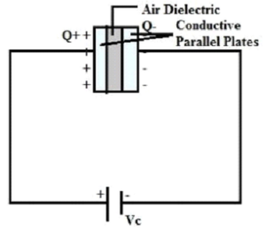

When current flows into the capacitor, it stores energy in the form of an electrostatic field. When the current flows out, the stored energy decreases, and the voltage across the plates drops.
Permittivity of Air Capacitor
Permittivity is a property of a material that measures its resistance to the formation of an electric field. It is denoted by the Greek symbol ε (epsilon) and measured in farads per meter.
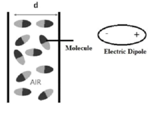

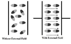
In an air capacitor, the dielectric medium is air, whose relative permittivity is approximately 1.0006, which is very close to unity. When an external electric field is applied, air molecules slightly polarize and generate an opposing electric field. This opposition is known as permittivity.

The capacitance of a parallel plate capacitor is given by:
C = ε × A / d
Where:
- A is the area of one plate
- d is the distance between the plates
- ε is the permittivity of the dielectric medium
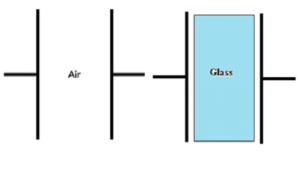

Materials with higher permittivity yield higher capacitance values, while materials with lower permittivity, such as air, result in lower capacitance.
Characteristics of Air Capacitor
- Air capacitors are non-polarized and suitable for AC applications
- Capacitance range is typically from 100 pF to 1 nF
- Maximum operating voltage depends on physical plate spacing
- Lower dielectric strength compared to other dielectric materials
- Low dielectric losses
Advantages of Air Capacitor
- Very low leakage current
- High insulation resistance
- Excellent stability
- Low dissipation factor
- Simple construction
Disadvantages of Air Capacitor
- Large physical size
- Limited capacitance range
- Higher cost
- Occupies more space compared to other capacitors
Applications of Air Capacitor
- Used in LC resonant circuits
- Radio frequency tuning circuits
- Antenna tuning and impedance matching networks
- Frequency mixers
- Low-loss RF applications