

Introduction
Most real-world physical quantities such as temperature, pressure, sound, and light exist in analogue form. However, digital processors like microcontrollers and microprocessors cannot directly process analogue signals. Therefore, an intermediate device is required to convert analogue data into digital form. This device is known as an Analog to Digital Converter (ADC).
An ADC converts analogue voltages into binary values consisting of 1s and 0s. Most ADCs accept input voltages such as 0–10 V or −5 V to +5 V and produce digital outputs suitable for digital processing systems.
What is an Analog to Digital Converter?
An Analog to Digital Converter (ADC) is an electronic integrated circuit that converts a continuous analogue signal into a discrete digital signal. It is commonly written as ADC, A/D, or A to D converter. ADC performs the reverse operation of a Digital to Analog Converter (DAC).


ADC performance mainly depends on two parameters:
- Sampling Rate: Speed at which the analogue signal is converted into digital form.
- Resolution: Accuracy of conversion, represented in bits.
Modern ADCs offer high speed, excellent linearity, low power consumption, and high signal-to-noise ratio (SNR), making them suitable for industrial, communication, and measurement systems.
ADC Block Diagram
An ADC mainly consists of four blocks: Sample, Hold, Quantizer, and Encoder.
Sample
The analogue signal is sampled at precise intervals of time. The sampling frequency must be selected carefully based on system requirements.
Hold
The hold circuit maintains the sampled amplitude constant until the next sample is taken.
Quantization
This stage converts the continuous amplitude signal into discrete levels.
Encoder
The encoder converts the quantized signal into binary form suitable for digital devices.
Analog to Digital Conversion Process
The ADC samples the input analogue signal and converts it into digital form using fixed precision. The accuracy of conversion depends on sampling rate and quantization level. According to the Nyquist theorem, the sampling frequency must be at least twice the maximum frequency of the input signal to avoid distortion. There are numerous techniques for converting analogue signals to digital signals.
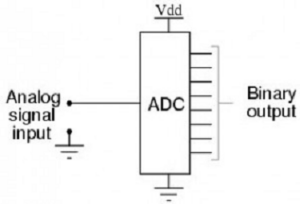
These converters are more commonly used as an intermediate device to convert signals from analogue to digital form and display output on an LCD via a microcontroller. An A/D converter’s goal is to determine the output signal word corresponding to an analogue signal. We are now going to see an ADC of 0804. It is an 8-bit converter powered by a 5V supply. It can only accept one analogue signal as input.

The digital output range is 0-255. A clock is required for ADC to function. The time required to convert an analogue value to a digital value is determined by the clock source. CLK IN pin no.4 can be connected to an external clock. To use the internal clock, an RC circuit is connected between the clock IN and clock R pins. Pin2 is the input pin – a high to low pulse transports data from the internal register to the output pins following conversion. Pin 3 is a Write pin, which sends a low to high pulse to the external clock. Pins 11 through 18 are data pins that range from MSB to LSB.
The analogue signal is sampled by the Analog to Digital Converter on each falling or rising edge of the sample clock. The ADC receives the analogue signal, measures it, and converts it to a digital value in each cycle. The ADC approximates the signal with fixed precision to convert the output data into a series of digital values.
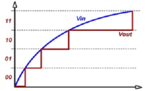
The accuracy of the digital value that captures the original analogue signal in ADCs is determined by two factors. These are the quantization level, also known as the bit rate, and the sampling rate. The diagram below depicts the analog-to-digital conversion process. The bit rate determines the resolution of the digitized output, as shown in the figure below, where a 3-bit ADC is used to convert the analogue signal.


Assume that a one-volt signal must be converted from digital to analogue using the 3-bit ADC shown below. As a result, there are a total of 23=8 divisions available for producing 1V output. This result 1/8=0.125V is known as the minimum change or quantization level, and it is represented for each division as 000 for 0V, 001 for 0.125, and 111 for 1V.
We can improve signal precision by increasing the bit rates to 6, 8, 12, 14, 16, and so on. As a result, bit rate or quantization produces the smallest output change in the analogue signal value as a result of a change in digital representation.
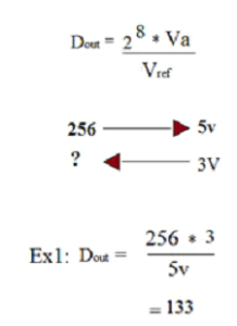
Suppose if the signal is about 0-5V and we have used 8-bit ADC then the binary output of 5V is 256. And for 3V it is 133 as shown below.

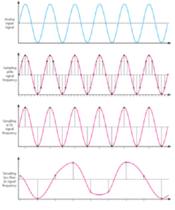
If the input signal is sampled at a different frequency than the desired one, it has a 100% chance of being misrepresented on the output side. As a result, another critical aspect of the ADC is the sampling rate. According to the Nyquist theorem, acquired signal reconstruction introduces distortion unless it is sampled at (minimum) twice the rate of the signal’s largest frequency content, as shown in the diagram. In practice, however, this rate is 5-10 times the maximum frequency of the signal.

Factors Affecting ADC Performance
- Signal-to-Noise Ratio (SNR): Indicates noise-free resolution.
- Bandwidth: Determined by sampling rate.
Types of Analog to Digital Converters
- Dual Slope ADC
- Flash ADC
- Successive Approximation ADC (SAR)
- Semi-Flash ADC
- Sigma-Delta ADC
- Pipelined ADC
Dual Slope ADC
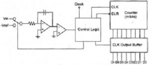

This ADC uses an integrator and counter. It is accurate but slow and moderately priced.
Flash ADC
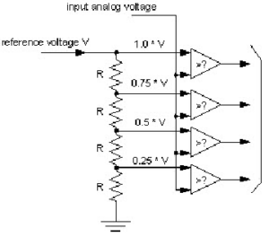

Flash ADCs use multiple comparators in parallel, making them extremely fast but expensive.
Successive Approximation ADC
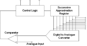

SAR ADCs use binary search logic and offer a good balance between speed and accuracy.
Sigma-Delta ADC
These ADCs provide very high resolution and are widely used in audio applications.
Pipelined ADC
Pipelined ADCs provide high speed with moderate resolution and are widely used in communication systems.
Examples of ADC
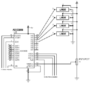
ADC0808
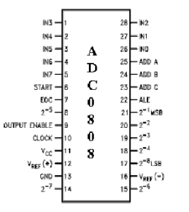

The ADC0808 is an 8-bit ADC with eight analogue input channels. It operates with a 5V power supply and is commonly used with microcontrollers.
Features
- 8-channel multiplexer
- TTL compatible outputs
- Low power consumption
- No zero or full-scale adjustment required

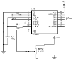
ADC0804
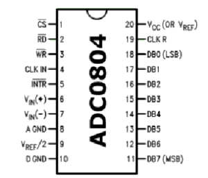

The ADC0804 is an 8-bit ADC with a single analogue input and internal clock generation capability.
Key Features
- 0–5V input range
- 8-bit resolution
- On-chip clock generator
- Compatible with microcontrollers

ADC Evaluation Parameters
- DC Offset Error
- DC Gain Error
- Power Dissipation
- SNR
- Total Harmonic Distortion (THD)
- Integral Non-Linearity (INL)
- Differential Non-Linearity (DNL)
Applications of Analog to Digital Converter
- Temperature measurement systems
- Digital oscilloscopes
- Mobile phones for voice processing
- Medical equipment such as MRI and X-ray machines
- Digital cameras and video recording devices
- Audio signal conversion
- Industrial automation and control systems
Conclusion
Analog to Digital Converters play a vital role in modern digital systems by enabling analogue signals to be processed digitally. With various types and configurations available, ADCs are used in almost every electronic device today. Selecting the appropriate ADC depends on resolution, speed, cost, and application requirements.