

Introduction
In fluid power, HVAC, and industrial process control, monitoring and controlling system pressure is essential for operational safety and automated workflow. A pressure switch is a contact sensor designed to detect changes in fluid or gas pressure, automatically opening or closing electrical contacts when a specific pressure threshold is reached.
What is a Pressure Switch?
A pressure switch is an electromechanical or solid-state device that monitors fluid, gas, or hydraulic pressure. It acts as an automated trip mechanism in a system: when pressure reaches a predetermined high limit (the cut-out point) or drops to a designated low limit (the setpoint), the switch changes state to start or stop pumps, open solenoids, or trigger warning alarms.




Pressure switches serve two main functions: maintaining system reservoir pressure within safe operating limits and protecting heavy equipment from damage caused by overpressurization or dry-running conditions.
Pressure Switch Pin Configuration & Electrical Contacts
Industrial pressure switches typically utilize a Single Pole Double Throw (SPDT) or Double Pole Double Throw (DPDT) contact configuration:

- Common (COM): The primary input terminal connected to the incoming power source or control circuit.
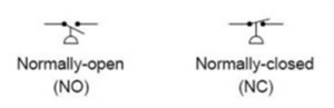
- Normally Closed (NC): Connected to COM when system pressure is below the setpoint. As pressure reaches the set threshold, this contact opens to cut power to fill pumps or heaters.
- Normally Open (NO): Disconnected from COM under normal/low pressure. When pressure rises to the trip point, this contact closes to energize discharge valves or trigger alarms.
Internal Construction and Key Components
A mechanical pressure switch consists of precision components designed to balance mechanical force against fluid pressure:
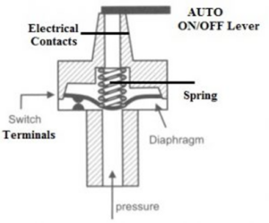
- Sensing Element: The primary component exposed to process fluid. Depending on the pressure range, this can be a flexible polymer diaphragm, metallic bellows, bourdon tube, or high-pressure piston.
- Adjustment Spring & Nut: A heavy-duty compression spring that sets the trip threshold (setpoint). Tightening the adjustment nut increases the force required to actuate the switch.
- Micro Switch / Contacts: A snap-action electrical switch mechanism with silver or gold-plated contacts rated for industrial electrical loads.
- AUTO/OFF Operating Lever or Knob: A manual override lever that allows technicians to cut power to connected equipment during routine maintenance.
- Enclosure & Cable Gland: A protective housing, often rated to IP66, IP68, or explosion-proof/flameproof standards for harsh industrial environments.
Working Principle of a Pressure Switch
The operation of a mechanical pressure switch relies on a force balance between fluid pressure and internal spring tension:
- Pressure Rise (Set Point): Process fluid enters the pressure port and acts directly against the sensing diaphragm or piston. As fluid pressure increases, it exerts an upward force against the calibrated adjustment spring. When this force exceeds the spring tension, the diaphragm flexes, driving an internal pushrod upward to trip the snap-action micro switch (changing contacts from NC to NO or vice-versa).
- Pressure Fall (Reset / Cut-Out Point): As fluid pressure drops, spring tension overcomes the fluid force, pushing the diaphragm back to its resting state and resetting the electrical contacts.
- Deadband (Hysteresis): The difference between the actuation pressure (setpoint) and the deactuation pressure (reset point). This offset prevents rapid, unwanted cycling (“chattering”) of the connected pump or motor.
Pressure Switch Circuit Using Force Sensing Resistor (FSR)
In electronic applications where physical force or surface load needs to trigger an AC appliance or relay, a force-sensing resistor (FSR) is combined with an operational amplifier comparator circuit:
When force is applied to the FSR, its internal resistance drops dramatically from several mega-ohms down to under 100 ohms. Connected in a voltage divider network with a reference resistor, this resistance drop raises the voltage at the non-inverting terminal of an op-amp comparator (such as an LM193). Once this voltage exceeds the reference voltage set by a potentiometer at the inverting terminal, the comparator output goes HIGH, turning on an NPN transistor (e.g., 2N2222) to energize a 12V relay and power the load.
Standard Technical Specifications
| Parameter | Typical Specification Range |
|---|---|
| Operating Pressure Range | -1 Bar (Vacuum) up to 250 Bar (Hydraulic) |
| Contact Electrical Rating | 5A, 10A, or 15A at 125V / 250V AC |
| Process Connection Threads | 1/4″, 3/8″, 1/2″, or 3/4″ BSP or NPT (Male/Female) |
| Switch Configurations | 1 SPDT, 2 SPDT, or DPDT snap-action contacts |
| Sensing Element Types | Diaphragm, Bellows, Capsule, Bourdon Tube, Piston |
| Ingress Protection Rating | Weatherproof IP66 / IP68 or Flameproof / Explosion-Proof |
| Max Operating Temperature | Up to +180°C |
Comparison: Mechanical vs. Electronic Pressure Switches
| Feature | Mechanical Pressure Switch | Electronic Pressure Switch |
|---|---|---|
| Operating Power | Passive device; requires no external power | Requires external power supply (12V–24V DC) |
| Display & Readout | No visual pressure display | Digital LED/LCD pressure readout |
| Switching Speed | Snap-action mechanical contact movement | Solid-state electronic switching (PNP/NPN) |
| Adjustability | Manual spring adjustment screw | Digital keypad setting for setpoint and deadband |
| Vibration Immunity | Susceptible to spring fatigue under heavy vibration | High resistance to mechanical shock and vibration |
How to Calibrate a Pressure Switch
To ensure system accuracy and verify proper deadband function, pressure switches require periodic calibration using a controlled pressure source and a digital multimeter:
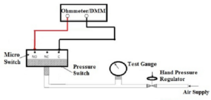

- Connect to Pressure Source: Mount the switch to a calibrated hand pressure pump equipped with a high-precision reference gauge.
- Wire Continuity Tester: Connect a digital multimeter set to continuity/resistance mode across the Common (COM) and Normally Open (NO) or Normally Closed (NC) terminals.
- Check Increasing Setpoint: Gradually increase air or hydraulic pressure using the hand pump until the multimeter indicates a contact state change (e.g., OPEN to SHORT). Record this exact pressure as the Increasing Setpoint.
- Check Decreasing Reset Point: Increase pressure slightly past the trip threshold, then slowly bleed off pressure until the multimeter resets to its original state. Record this value as the Decreasing Reset Point.
- Calculate Deadband: Subtract the decreasing reset point from the increasing setpoint. Verify that this calculated deadband value falls within the manufacturer’s specified maximum limits. If out of tolerance, adjust the internal spring tension screw.
Advantages and Disadvantages
Advantages:
- Direct Load Control: High-amp micro switches can directly trigger large pump motors and contactors without needing external relays.
- Passive Operation: Mechanical designs function reliably without auxiliary control power.
- High Durability: Rugged metal enclosures withstand outdoor weathering, high pressures, and corrosive atmospheres.
- Wide Media Compatibility: Available with stainless steel, brass, or Hastelloy wetted parts suitable for water, oil, gases, and steam.
Disadvantages:
- Mechanical Wear: Diaphragms and spring assemblies degrade over millions of duty cycles.
- Hysteresis Limitations: Fixed mechanical deadbands may lack the fine precision needed in strict process automation loops.
- Pulsation Sensitivity: Hydraulic pressure spikes can cause contact chatter unless dampeners or snubbers are installed.
Industrial and Commercial Applications
Pressure switches perform vital safety and control functions across numerous industries:
- Compressors & Pneumatics: Automatically cycle air compressor motors ON and OFF based on receiver tank pressure.
- Pumping Systems: Regulate booster pumps in municipal water supply networks, well pumps, and fire sprinkler systems.
- HVAC & Boiler Controls: Monitor draft pressure in furnaces, steam boiler safety cut-offs, and refrigerant pressure in chillers.
- Heavy Machinery & Industrial Manufacturing: Control hydraulic clamp pressure on injection molding machines, stamping presses, and robotic welders.
- Automotive & Transportation: Manage engine oil pressure warnings, train pneumatic braking circuits, and power steering assist loops.
- Medical Equipment: Monitor gas delivery pressure in hospital oxygen lines, ventilators, and surgical suction units.