

Arduino Uno is a microcontroller board based on the ATmega328P. It has sets of digital and analog pins that may be interfaced with various expansion boards. The board has 14 digital input/output pins (of which 6 can be used as PWM outputs), 6 analog inputs pins which are programmable with Arduino IDE (Integrated Development Environment) with a use of USB cable, a 16 MHz ceramic resonator (CSTCE16M0V53-R0), a USB connection, a power jack, an ICSP header, and a reset button. It contains everything needed to support the microcontroller; simply connect it to a computer with a USB cable or power it with an AC-to-DC adapter or 5-volt battery to get started. Though it accepts voltages between 7 to 20 volts of power.
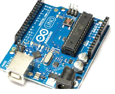


The word “UNO” means “one” and was first chosen to marks as the initial release of the Arduino family. The Uno board is the first in series of USB-based Arduino boards. The Arduino Uno has the language on which it is programmed. it works on C and C++ language and scripted using JAVA language. The ATmega328 on the board is already programmed with a bootloader that allows uploading new code to the board without the use of an external hardware programmer.
The Arduino Uno is the best board to get started with electronics and coding if this is your first experience tinkering with the platform the UNO is the most used documented board of the whole Arduino family.
Technical Specification
- Microcontroller: MicrochipATmega328P
- Operating Voltage: 5 Volts
- Input Voltage: 7 to 20 Volts
- Digital I/O Pins: 14 (of which 6 can provide PWM output)
- UART: 1
- I2C: 1
- SPPI: 1
- Analog Input Pins: 6
- DC Current per I/O Pin: 20 mA
- DC Current for 3.3V Pin: 50 mA
- Flash Memory: 32 KB of which 0.5 KB used by bootleader
- SRAM: 2 KB
- EEPROM: 1 KB
- Frequency: 16 MHz
- Length: 68.6 mm
- Width: 53.4 mm
- Weight: 25 g
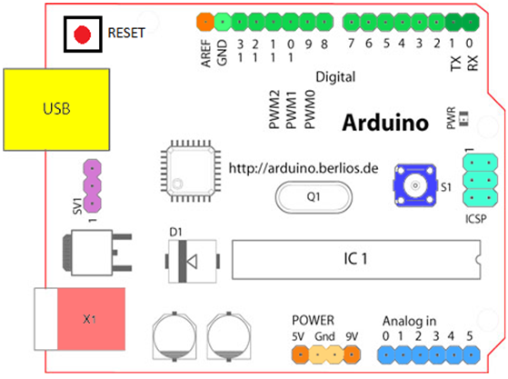

Digital Input /Output Pins (light green color)
As we know that Arduino UNO has a total of 14 digital input/output pins. Out of these 14 pins, 6 input/output pins (3,5, 6, 9, 10 and 11) are PWM enabled and 2 pins (12 and 13) are Serial Peripheral Interface (SPI). 2 Serial pins (0 and 1) which are used for transmitting (TX) and receive (RX) data. External Interrupts pins (2 and 3) can be configured to trigger an interrupt on low value. Pin 7 is connected to the reset line of the Bluetooth module. Pin 13 is a built-in LED, when the pin is high value the led is ON, and when the pin is in low value it is OFF.
Analog Input Pins (light blue)
As we can see in the above fig. pins as 0, 1, 2, 3, 4, 5 are analog input pins. Some of the analog pins can be used as digital pins.
Power Pins
- VIN:The pins from where the input voltage s given to the Arduino board using an external power source. Sometimes it is labeled as 9V
- 5V: The regulated power supply used is used to power the microcontroller and other components on the board.
- GND: Ground pins.
Other Pins
- AREF: Reference voltage for analog inputs.
- RESET: Typically used this reset button to shields which block the one on the board.
- External Power Supply: X1|( pink color)
- Toggles External Power and USB Power: SV1(purple)
- USB: Used to power the board ( yellow)
- Reset Button: S1(dark blue)
Advantages
- It is an open-source microprocessor board where software and hardware programs are easily accessible and very flexible to be customized.
- It is easy to use; it can connect to computers or laptops using USB cables.
- It has very simple language, as it is specially designed for beginners in this electronic world.
- It is a great tool for developing interactive projects.
- It is inexpensive around 30 euros per board and comes with free authoring software.
Application
- Arduino UNO can be used in any system or projects where a microcontroller is required.
- Bluetooth controls Home Automation.
- Autonomous vehicle.
- IoT enables Home Automation.
- Robotic Mechanism.
- Remote-based Home Automation.
- Developing projects based on code-based control.
- Designing basic circuit designs.