


The bridge rectifier is used to convert the AC i.e. alternating current to DC i.e. direct current. Many electronic circuits require a DC power supply to power up various electronic components from the available AC power source. Among the entire rectifier, this bridge rectifier is the most efficient rectifier circuit.
The rectifier is classified into three type
- Half wave
- Full-wave
- Bridge rectifier
So bridge rectifiers are circuit that converts AC current to DC current using diodes arranged in the bridge circuit configuration. It is comprised of one or more diodes. The output wave generated is of the same polarity irrespective of the polarity at the input. Depending on the load current requirement a proper bridge rectifier is selected. While selecting a rectifier power supply for appropriate electronic circuits the components rating and specifications, breakdown voltage, temperature range, transient current rating, forward current rating, etc. are considered.

Construction

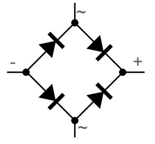
The circuit is constructed by using four diodes namely D1, D2, D3, D4 along with a load resistor. It is a closed-loop pattern design to convert the AC current to DC current efficiently. The main advantage of this design is the lack of a center-tapped transformer. So because of this the cost, as well as size, will be reduced.
When the input signal is applied across the two terminals like A and B then the output DC signal can be attained across the RI. This load resistor is connected between the two terminals C and D. the arrangement of the diode is done in such a way that the electricity will be generated by the two diodes throughout every cycle. So the pair of diodes like D1 and D3 will generate electric current throughout the positive half cycle and similarly D2 and D4 diode will conduct electric current during the negative half cycle.
Bridge rectifier diagram


The main advantage of the bridge rectifier is that it produces almost double the output voltage as compared to the full-wave rectifier using a center-tapped transformer. As this circuit does not need a center-tapped transformer therefore it resembles a low-cost rectifier. Thus the bridge rectifier circuit diagram consists of various stages of the device like a transformer, diode bridge, filtering, and regulators. So generally all these blocks combination is called a regulated DC power supply.
Working
When the AC signal is applied across the bridge rectifier, terminal A becomes positive and terminal B becomes negative during the positive half cycle. Because of this the diode D1 and D3 become forward biased while D2 and D4 become reverse biased.
During the negative half-cycle, terminal B becomes positive while terminal A becomes negative. This causes diode D2 and D4 to become forward biased and diode D1 and D3 to be reverse biased.
Therefore we have noticed that the current flow across load resistor RL is the same during the positive half cycle and the negative half cycle. And also seen that the output polarity of the signal may be either completely positive or negative. If the direction of the diode is reversed then we get a complete negative DC voltage otherwise it is completely positive
Thus bridge rectifier allows electric current during both positive and negative half cycles of the input AC signal.
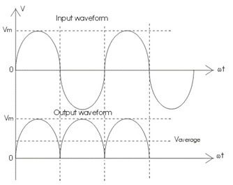
The output waveform of the bridge rectifier is shown in figure

Advantage
- A bridge rectifier has a higher efficiency than the half-wave rectifier.
- A smooth and steady output is obtained from a bridge rectifier.
- The feature of producing both positive and negative half cycle of the input AC signal is not found in half-wave rectifier.
Disadvantage
- Bridge rectifier is complex when compared to a half-wave rectifier. Thus bridge rectifier uses 4 diodes while the half rectifier and center tapped full wave rectifier use only 2 diodes.
- When more than one diode is used more power loss occurs.
- Voltage drop is higher in a bridge rectifier.