

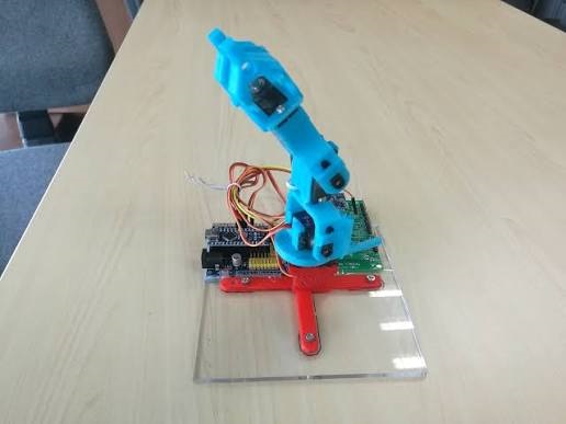

Robotic arms built around Arduino and hobby servos are a familiar student project. This design takes the idea a step further: instead of programming fixed joint movements in advance, the arm is controlled live by a wearable glove that senses how the operator’s fingers and wrist are moving, and sends that information wirelessly to the arm. A force sensor on the arm’s gripper then reports grip pressure back to a vibration motor on the glove, so the operator gets real, physical feedback on how hard the arm is gripping an object.


The project is built from two communicating units: a master unit worn as a glove, and a slave unit that is the robotic arm itself. Between them runs a 2.4GHz wireless link that carries motion commands one way and force feedback the other way.

Block diagram

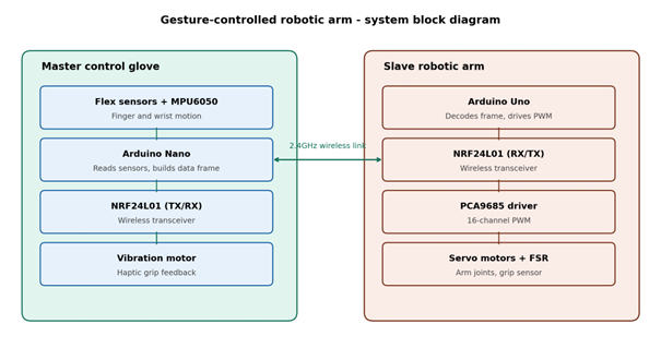
The master glove reads finger bend and wrist orientation, packages this into a data frame, and transmits it over NRF24L01. The slave arm receives the frame, decodes joint angles, and drives its servos through a PWM driver. A force sensor at the gripper sends grip-force data back over the same wireless link, which the glove uses to drive a vibration motor.
Working principle
- Five flex sensors, one per finger, are wired as voltage dividers whose output voltage changes as each finger bends.
- An MPU6050 inertial sensor mounted on the back of the hand tracks wrist tilt and rotation over I2C.
- An Arduino Nano on the glove reads all sensor values, scales them to servo-angle ranges, and packs them into a compact data packet.
- The packet is transmitted over an NRF24L01 2.4GHz transceiver to a matching NRF24L01 on the arm.
- An Arduino Uno on the arm receives the packet and forwards target angles to a PCA9685 16-channel PWM driver over I2C.
- The PCA9685 drives the base, shoulder, elbow, wrist and gripper servos, reproducing the operator’s hand and arm motion in real time.
- An FSR402 force sensor at the gripper tip measures contact pressure whenever the arm grips an object.
- This force reading is sent back to the glove over the same wireless link and used to drive a small vibration motor, giving the operator a physical sense of grip strength.
Circuit design and connections
Master unit: control glove
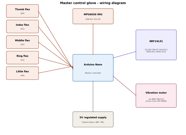
The Arduino Nano is the hub of the glove circuit. Each flex sensor forms a voltage divider with a fixed resistor and feeds an analog pin (A0 to A3 and A6). The MPU6050 communicates over I2C using the Nano’s A4 (SDA) and A5 (SCL) pins. The NRF24L01 uses the SPI bus (pins D11, D12, D13) plus two extra digital pins for CE and CSN (D8 and D7). The vibration motor is switched through an NPN transistor (2N2222) driven from a PWM-capable pin (D9), since the motor draws more current than an Arduino pin can safely supply directly.

Slave unit: robotic arm
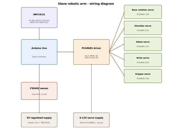
The Arduino Uno mirrors the same SPI connections for its NRF24L01 module (D7, D8, D11, D12, D13) and the same I2C pins (A4, A5) to talk to the PCA9685 driver. The PCA9685 fans out to five servo channels covering base rotation, shoulder, elbow, wrist and gripper, and is powered from a separate 6 to 12V supply so that servo current spikes do not disturb the logic supply. The FSR402 sits in a simple voltage-divider circuit connected to a free analog pin (A0) on the Uno.

Power supply notes
- Keep servo power (6-12V) and logic power (5V) on separate rails, joined only at a common ground, to avoid brownouts resetting the Arduinos when servos draw current.
- Add a decoupling capacitor (about 470uF to 1000uF) across the servo supply rail near the PCA9685 to smooth current spikes.
- If range beyond a few metres is needed, use the NRF24L01+PA+LNA variant with an external antenna instead of the basic module.
Components used
| Item | Qty | Notes |
| Arduino Nano | 1 | Master (glove) controller |
| Arduino Uno | 1 | Slave (arm) controller |
| NRF24L01 transceiver (+PA/LNA for range) | 2 | One per side, SPI interface |
| MPU6050 IMU | 1 | Wrist orientation, I2C |
| Flex sensors (2.2 inch) | 5 | One per finger, with 10k ohm divider resistor |
| PCA9685 16-channel PWM driver | 1 | Drives all arm servos over I2C |
| MG996R servo or equivalent | 4-5 | Base, shoulder, elbow, wrist |
| SG90 micro servo | 1 | Gripper |
| FSR402 force sensor | 1 | Mounted on gripper fingertip |
| Coin vibration motor + 2N2222 transistor | 1 each | Haptic feedback driver on glove |
| 5V regulated supply | 1 | Logic side, both Arduinos and NRF modules |
| 6-12V supply, 5A or higher | 1 | Servo power, separate from logic rail, common ground |
Applications
- Teleoperation of a robotic arm in hazardous environments (electrical panels, chemical handling, radiation zones)
- Assistive and rehabilitation devices, where a glove interface helps a user control an external gripper
- Educational demonstrations of wireless control, sensor fusion and closed-loop haptic feedback
- Remote-handling stations in labs or industrial settings where direct manual access is restricted
- A base platform for research into gesture-based robot control and human-machine interfaces
Possible extensions
- Replace the glove’s flex sensors with camera-based hand tracking (for example, MediaPipe) to remove wearable hardware
- Add an OLED display or companion app showing live grip force and joint angles for logging or demonstration
- Extend to a two-arm (bimanual) system for more complex manipulation tasks
- Add closed-loop PID control on each joint using servo feedback potentiometers for smoother motion
Conclusion
This project moves beyond a simple pre-programmed robotic arm by adding two subsystems that are genuinely useful for engineering students to build and debug: a wearable gesture-sensing glove, and a bidirectional wireless link that carries both motion commands and force feedback. It offers a natural entry point into topics like sensor calibration, wireless protocol design and closed-loop feedback control, while remaining buildable with common hobbyist-level components.