

Introduction
According to the Logic OR Function, an output becomes TRUE if one or more input conditions are TRUE. The order of these inputs does not affect the final result.
For instance, A + B = B + A. The Logic OR Function in Boolean algebra follows the Commutative Law, just like the AND function, allowing the order of variables to be interchanged.
In contrast to the Exclusive-OR (XOR) function, the OR function is sometimes called the Inclusive OR function because it produces a high output even when both inputs are high.

A logic gate that performs the logical OR operation is called an OR gate. The OR gate outputs a HIGH signal (1) if one or both inputs are HIGH (1). If neither input is HIGH, the output is LOW (0). Like an AND gate, an OR gate can have multiple input terminals but only one output terminal.
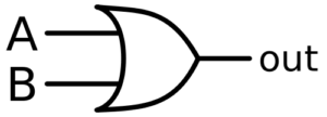

Symbol of OR Gate
The logical OR gate essentially determines the maximum between two binary inputs, whereas the AND gate determines the minimum. A simple two-input OR gate can be implemented using diodes, as shown below.
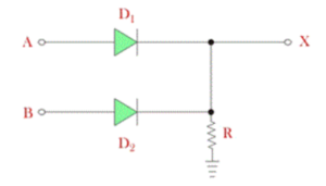

When both inputs A and B are applied with 0V, no voltage appears at the output (X). When +5V is applied to any input, the corresponding diode becomes forward-biased and conducts, allowing approximately +4.3V to +4.4V to appear at the output X. This voltage level is considered as logical 1.
If both inputs are at +5V, both diodes conduct, and the output still remains at approximately +4.3V (logical 1).
When both inputs are grounded (0V), the diodes are reverse-biased, and the output remains at 0V (logical 0).
The Boolean expression for a logic OR gate is based on logical addition and is represented by the plus symbol (+). For a two-input gate, the output is represented as:
A + B = Q
Switch Representation of the OR Function
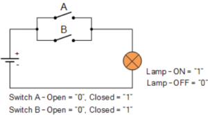

In the switch analogy, two switches A and B are connected in parallel. Closing either switch allows current to flow, turning the lamp ON. In Boolean terms, this represents a condition where the output is TRUE if any of the inputs is TRUE.
Thus, the logic OR function is equivalent to a parallel electrical circuit. The output is TRUE when one or more inputs are TRUE.
Truth Table of OR Function
| Input A | Input B | Output (A + B) |
|---|---|---|
| 0 | 0 | 0 |
| 0 | 1 | 1 |
| 1 | 0 | 1 |
| 1 | 1 | 1 |
OR Gate IC Packages
Common integrated circuit (IC) packages for logic OR gates include:
- TTL 74LS32 – Quadruple 2-input positive OR gates
- CMOS 4071 – Quad 2-input OR gates
Like the AND gate, OR gates can also be cascaded to create circuits with more input conditions. Such configurations are often used in applications like security alarm systems, where triggering any one of several zones (Zone A, Zone B, or Zone C) can activate an alarm.
Conclusion
The Logic OR Gate is one of the key components in digital electronics. It outputs a HIGH signal when any input condition is TRUE, making it essential for circuits that respond to multiple possible triggers. Understanding its working, Boolean expression, and truth table is fundamental to mastering digital logic design.