

Introduction
In electrical engineering and industrial automation, switches play an essential role in opening, closing, and routing current paths within a circuit.
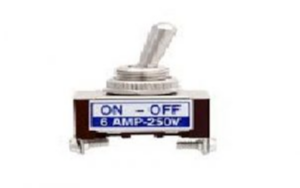



A toggle switch is an electromechanical switch featuring a manually operated lever or handle that flips forward and backward to control electrical connections.

What is a Toggle Switch?
A toggle switch is a versatile power and control switch that changes circuit states when an external lever (toggle) is moved. It acts as an ON/OFF or multi-way selector in both AC and DC applications, controlling power distribution to motors, lighting, and control systems.
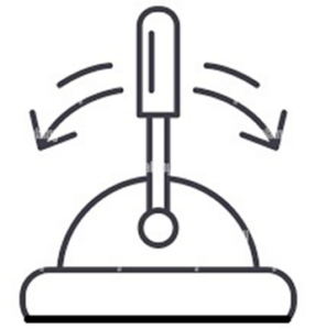

Toggle switches are widely deployed in industrial machinery control panels, commercial aircraft cockpits, telecommunications infrastructure, and automotive electrical systems.
Toggle Switch Pin Configuration (SPDT)
A standard Single Pole Double Throw (SPDT) toggle switch features three primary terminal pins:
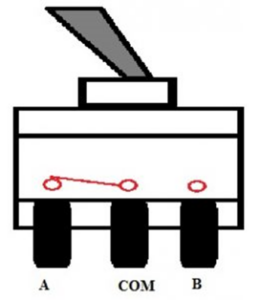

- Pin 1 (Output A): The first output terminal connected to Load 1.
- Pin 2 (COM / Common Input): The main input terminal connected to the power source.
- Pin 3 (Output B): The second output terminal connected to Load 2.
Standard Technical Specifications
| Parameter | Typical Specification Range |
|---|---|
| Contact Resistance | 10 m$\Omega$ (Max) |
| Insulation Resistance | 1,000 M$\Omega$ (Min) at 500V DC |
| Dielectric Strength | 1,000 $V_{rms}$ at sea level |
| Operating Temperature | -30°C to +85°C |
| Current Rating | 100 mA (Logic Level Gold contacts) to 15A/20A (Power Silver contacts) |
Internal Construction and Key Components
A robust toggle switch consists of several precision mechanical components housed in an insulated casing:
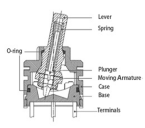

- Actuator Lever: The external metallic or resin handle moved by the operator to switch positions.
- Internal Spring & Plunger: Located inside the lever assembly, the spring exerts constant outward pressure against the base to provide tactile snap-action feedback.
- O-Ring Seal: Elastomeric rubber ring that seals the joint between the case, lever, and base to prevent moisture and dust ingress.
- Moving Armature (Contact Bridge): A U-shaped conductive contact arm that slides across output terminals when the lever is actuated.
- Outer Case & Base: High-strength resin or metal housing that secures internal mechanics and exposes connection terminals at the bottom.
Working Principle and Circuit Wiring Diagram
The operation of an SPDT toggle switch relies on a mechanical over-center spring mechanism. Flipping the lever shifts the internal moving armature to bridge the common terminal (COM) with either Output A or Output B:
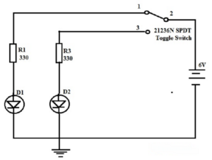

- Connect the positive power rail (e.g., +6V DC) to Pin 2 (COM).
- Connect Pin 1 (Output A) through a current-limiting resistor $R_1$ to an LED ($D_1$).
- Connect Pin 3 (Output B) through a current-limiting resistor $R_2$ to a second LED ($D_2$).
When the lever is toggled toward Pin 1, the internal armature connects COM to Pin 1, illuminating LED $D_1$ while $D_2$ remains OFF. Flipping the lever toward Pin 3 shifts the connection from COM to Pin 3, turning OFF $D_1$ and instantly lighting $D_2$.
Comparison of Common Industrial Switches
| Switch Type | Actuation Mechanism | Tactile Feedback | Primary Application Area |
|---|---|---|---|
| Toggle Switch | Extended lever handle | Audible click & mechanical latch | Aerospace, industrial panels, heavy equipment |
| Rocker Switch | Flat see-saw button | Smooth rocking pressure | Power strips, household appliances, surge protectors |
| Push Button | In-and-out axial pressing | Momentary or latching plunger | Machine emergency stops, resets, elevators |
Advantages and Disadvantages
Advantages:
- High Mechanical Durability: Metal lever options provide long-lasting service under heavy industrial usage.
- Unmistakable Status Indication: Physical lever position provides clear visual confirmation of switch state even when power is off.
- Environmental Sealing: Easily fitted with rubber boot seals for IP67/IP68 water and dust resistance.
- Tactile Reliability: Strong internal snap action prevents contact bouncing and incomplete switching states.
Disadvantages:
- Protruding Profile: The extended lever can be accidentally bumped or tripped if unshielded.
- Acoustic Noise: Produces an audible clicking sound during actuation, which may be undesirable in quiet environments.
- Panel Space Requirements: Requires a lock-washer and rear panel clearance during installation.
Applications of Toggle Switches
Toggle switches are trusted across demanding industrial, military, and commercial sectors:
- Industrial Automation: Main power controls on conveyor systems, packaging machines, and process lines.
- Aerospace & Defense: Aircraft cockpit control panels, flight avionics, and military communication rigs.
- Automotive & Transportation: Auxiliary vehicle lighting, indicator toggles, and heavy truck control banks.
- Commercial Power Outlets: Residual Current Devices (RCDs) and industrial distribution boxes.
- Telecommunications & Audio: Logic-level switching in broadcast consoles and telecom hardware.