

Introduction
In automated machinery and industrial control systems, determining the exact physical position or travel bound of a moving component is critical.
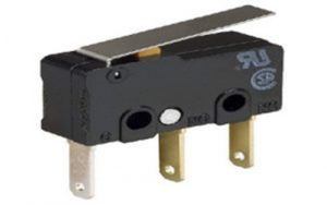



A limit switch is a heavy-duty electromechanical device activated by the physical force or presence of an object to make or break an electrical connection.
What is a Limit Switch?
A limit switch is an operational switch that detects the presence, position, speed, or end-of-travel limit of an object through direct physical contact. When a moving machine part hits the switch’s actuator, it trips the internal contact mechanism, triggering an electrical control signal to stop, slow down, or reverse motor movement.


Because limit switches feature rugged enclosures and high current switching capacities, they are widely installed across material handling systems, CNC machine tools, manufacturing assembly lines, and HVAC equipment.
Limit Switch Terminal Configuration
Standard limit switches utilize a Single Pole Double Throw (SPDT) contact block with three primary wiring terminals:
- Common (C / COM): The primary input terminal where the incoming power or control signal connects to the internal movable contact.
- Normally Closed (NC): Connected to the Common terminal when the switch is in its resting state. When an object actuates the lever, the NC path breaks (opens).
- Normally Open (NO): Disconnected from Common when the switch is at rest. When physical pressure trips the actuator, the internal mechanism snaps over to complete the path between C and NO.
Internal Construction and Key Components
Limit switches are engineered for extreme durability under severe environmental conditions. They consist of five main structural parts:
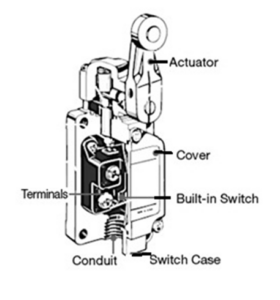

- Actuator Assembly: The external lever, roller, plunger, or whisker that receives physical force from moving machinery.
- Operating Head: Translates rotary, linear, or perpendicular mechanical motion into internal axial movement.
- Built-In Snap-Action Switch: A quick-make/quick-break spring mechanism housing conductive contacts (typically silver or copper alloy) that toggle states instantaneously.
- Heavy-Duty Switch Enclosure: Cast aluminum, stainless steel, or reinforced thermoplastic housing that provides IP65/IP67 mechanical and weather protection.
- Conduit Gland & Sealing Cover: Threaded base opening with rubber gaskets that seals cable entry points against oil, water, and debris.
Working Principle of a Limit Switch
The operation of a limit switch is governed by direct mechanical engagement and snap-action tripping points:
- Resting Position: When no target object contacts the actuator, internal return springs keep the movable contact seated against the NC terminal. Current flows uninterrupted to the standby circuit (e.g., status indicator light).
- Tripping Point Activation: As a target object (such as a conveyor box or CNC carriage) depresses the roller lever, internal mechanical force compresses an over-center spring.
- Snap-Action Changeover: Upon reaching the pre-set trip point distance, the spring instantly flips the contact arm. The NC path opens and the NO path closes in under 10 milliseconds.
- Reset Position: When the object moves away, the internal return spring forces the actuator back past its reset threshold, returning the electrical contacts to their original C-to-NC state.
Limit Switch Circuit Wiring & Indicator Operation
A fundamental limit switch control circuit uses a 12V DC power source, an 850$\Omega$ current-limiting resistor, a Red LED (Standby/Off state), and a Green LED (Actuated state):
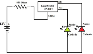

- The positive 12V DC power rail connects through the 850$\Omega$ resistor to the Common (C) terminal.
- The NC terminal wires directly to the positive anode of the Red LED.
- The NO terminal wires directly to the positive anode of the Green LED.
- The negative battery rail connects to the negative cathodes of both LEDs.
Unactuated State: Power flows from C $\rightarrow$ NC, illuminating the Red LED (indicating the machine carriage has not reached the boundary limit).
Actuated State: Once the machine hits the lever, the contact snaps from C $\rightarrow$ NO, turning off the Red LED and illuminating the Green LED (signaling target position reached).
Comparison of Industrial Limit Switch Actuator Types
| Actuator Type | Motion Type | Best Suited For |
|---|---|---|
| Roller Lever | Rotary / Cam action | Conveyor belts, high-speed passing objects, side-approach cams |
| Push Plunger | Direct linear compression | Short-stroke precision boundary stops, stamping presses |
| Flexible Whisker / Rod | Multi-directional deflection | Irregularly shaped targets, conveyor item counting, door sensing |
| Adjustable Roller Lever | Variable length rotary | Overhead cranes, heavy machinery with variable trip distances |
Advantages and Disadvantages
Advantages:
- High Current Switching: Can directly switch electrical loads up to 10A without requiring intermediate relay amplification.
- Immunity to Electrical Interference: Physical mechanical contacts are entirely immune to RF noise, ESD, or stray electromagnetic fields (EMI).
- Rugged Environmental Tolerance: Operates reliably in extreme temperatures, high-vibration zones, dust, and moisture.
- Visual & Tactile Reliability: Provides definitive mechanical feedback and clear visual confirmation of switch status.
Disadvantages:
- Mechanical Wear: Physical contact with targets causes surface friction wear over long-term operation.
- Operating Speed Limits: Not suitable for ultra-high-frequency non-contact sensing (e.g., speeds over 2,000 cycles per minute).
- Target Contact Impact: Requires physical force from the moving object, making it unsuitable for fragile or lightweight materials.
Industrial and Commercial Applications
Limit switches perform critical sensing, counting, and safety functions across diverse sectors:
- Material Handling Equipment: Stopping conveyor lines, controlling overhead crane travel limits, and positioning hoists.
- Elevators & Escalators: Floor-leveling accuracy, emergency over-travel safety cutoffs, and door safety-edge interlocks.
- HVAC Systems: Plenums and furnace high-limit temperature monitoring switches (activating blowers between 130°F and 160°F).
- Machine Tools & Manufacturing: Axis travel boundaries on CNC mills, metal presses, and packaging machinery.
- Automotive & Commercial Equipment: Car wash position sensing, garage door safety stops, and automated door panels.