

Introduction
Membrane switches have been widely available for over fifty years, with the very first membrane keypad introduced back in 1970. These switches are constructed from polycarbonate or polyester-based plastic films, featuring electronic circuits printed directly onto them using conductive silver or copper-filled inks.
Traditionally, these switches are designed with a spacer layer sandwiched between two conducting layers. The global market for membrane switches has seen substantial growth over the years, expanding from $4.2 billion in 2015 to an estimated $13 billion, highlighting their widespread adoption across modern consumer, industrial, and medical devices.


What is a Membrane Switch?
A membrane switch is a user-to-machine interface that allows operators to interact seamlessly with machinery, equipment, or electronic instrumentation. At its core, it is a printed electronic circuit that uses physical force to open and close an electrical path.
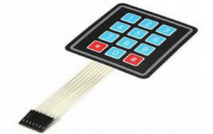

Membrane Switch
The internal circuitry of a membrane switch is most commonly screen-printed using conductive inks, typically composed of silver or carbon elements. These switches serve as critical hardware components that constitute modern Human-Machine Interfaces (HMIs), working alongside mechanical switches and touch screens.
Membrane Switch Design and Construction
These switches are constructed using multiple thin layers bonded together with pressure-sensitive adhesives or heat-sealing films. The main functional layers include the graphic overlay, adhesive layers, circuit layers, and tactile elements like metal domes. Below is a detailed breakdown of each layer and its purpose:
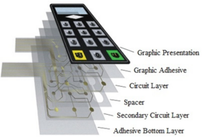

Membrane Switch Construction
1. Graphic Presentation Layer (Graphic Overlay)
The graphic presentation layer, or graphic overlay, is the outermost face of the switch. Polyester is typically preferred over polycarbonate for this layer due to its superior flexibility and chemical resistance. Depending on the device’s application, printed silicone rubber or premium polyester materials are used to form this top surface.
2. Graphic Adhesive Layer
This is the second layer of the switch assembly. It bonds the upper circuit layer directly to the overlying graphic display. This layer consists of a high-strength polyester substrate coated with double-sided adhesive.
3. Circuit Layer / PCB Layer
The primary circuit layer contains the printed electronic traces and houses the dome features of the switch. Conductive paths are embedded onto this layer using one of two primary industrial methods: photochemical etching or precision screen printing.
4. Spacer Layer
Positioned between the upper and lower circuit substrates, the spacer layer is made from heat-stabilized polyester. Its primary function is to keep the conducting layers separated when the switch is at rest. It features air-venting channels between the key spaces to prevent air entrapment and condensation when a key is pressed.
5. Secondary Circuit Layer
This optional, secondary circuit layer provides additional routing paths for complex electronics. It is typically a heat-stabilized polyester layer screen-printed with dielectric insulation and electrically conductive, silver-filled inks.
6. Rear Adhesive Layer
Positioned on the very back of the assembly, this final adhesive sheet permanently mounts the entire completed membrane switch package onto the final product enclosure or housing.
Key Features of Membrane Switches
- Completely Sealed Surface: Easy to clean, wash, and sterilize, making them perfect for medical environments.
- Low Profile Design: Seamless layout with no cracks or crevices to trap dirt or contaminants.
- Cost-Effective: Significantly more affordable than capacitive touch glass panels or heavy rubber keypad assemblies.
- Space-Saving: An ultra-thin profile preserves valuable interior space within compact product designs.
- Easy Integration: Can be effortlessly interfaced with modern microcontrollers and existing electronic control units.
- Versatile Graphics: Overlays can be digitally or screen-printed to replicate various textures like wood grain, metal, stone, or glass.
- Environmental Protection: Highly resistant to water ingress and easily treated for UV radiation protection.
- Advanced Enhancements: Can include built-in features such as tactile feedback domes, fiber-optic/electroluminescent backlighting, display windows, and integrated LEDs.
How Does a Membrane Switch Work?
A membrane switch relies on flexible layers working in unison. The user interacts with the top graphic overlay, which features visible keys aligned over underlying contact points. Conductive inks (like silver, graphite, or copper) are printed onto thin, flexible membrane sheets made of PET (polyethylene terephthalate).
Under normal conditions, an internal spacer layer keeps the upper and lower circuits apart, leaving the switch open. When a user applies physical pressure to a key, the top flexible membrane deforms, forcing the upper conductive ink trace to touch the lower trace. This completes the circuit for that specific key. The connected microcontroller or processing unit detects which circuit path closed, recognizes the corresponding key press, and triggers the intended machine output.
Membrane Switch Interfacing with Arduino Uno
Membrane switches frequently serve as numeric matrix keypads for calculations and input controls in engineering projects. They are available in standard configurations like 4×1, 4×3, or 4×4 matrix grids. Regardless of the grid size, they all operate under the same matrix scanning principle.
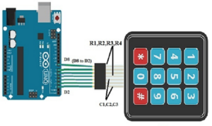

Membrane Switch Interfacing with Arduino Uno Board
When a button is pressed, it bridges a specific row line with a specific column line. For example, pressing Key 1 shorts Row 1 and Column 1 together. Pressing Key 2 shorts Row 1 and Column 2 together. An Arduino microcontroller scans these interconnected matrix lines to calculate the precise coordinates of the pressed key.
Wiring Connection Guide:
- Connect the membrane switch Row pins (R1 to R4) to the Arduino Uno’s digital pins D8 down to D5.
- Connect the column pins (C1 to C3 or C4) to the Arduino Uno’s digital pins D4 down to D2.
Once wired, you can upload a standard matrix keypad script using the Arduino IDE. The Arduino continually drives the row pins low or high while monitoring the column pins as inputs. If a column read changes state, the Arduino cross-references the active row with the active column to identify the exact key pressed and sends the value straight to the Serial Monitor.
Main Types of Membrane Switches
1. Tactile Membrane Switches
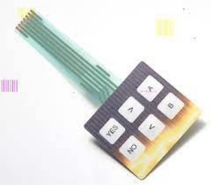

Tactile Membrane Switch
Tactile switches provide a distinct, physical “snap” sensation when pressed, giving the user tactile confirmation that the button was successfully actuated. This is accomplished by placing metal domes or hydroformed polyester domes directly beneath the graphic overlay layer.
2. Non-Tactile Membrane Switches
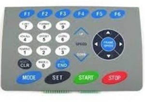

Non-Tactile
Non-tactile switches are highly reliable and economical, but they do not offer physical click feedback. To compensate for this, systems utilizing non-tactile switches typically incorporate alternative feedback mechanisms, such as an audible buzzer beep or a visual indicator light on a display screen.
3. Mixed Panels
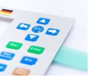

Mixed Panels
Mixed panels combine both tactile and non-tactile switches within a single interface panel. This setup is highly useful for industrial equipment layouts where secondary programming, hidden configuration keys, or maintenance buttons require large active touch zones without accidental click triggers.
4. PCB-Backed Membrane Switches
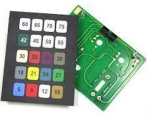

PCB Backed
In this construction style, the lower circuit layer is replaced by a rigid Printed Circuit Board (PCB). The rigid PCB serves a dual purpose: it acts as a robust structural backing plate and allows manufacturers to solder surface-mount components (SMDs), connectors, and chips directly onto the back of the switch unit.
Advantages and Disadvantages
Advantages: Outstanding moisture and weather resistance, low-profile aesthetics, minimal voltage requirements, robust electromagnetic (EMI/RFI) shielding, exceptional durability, and easy-to-sanitize flat surfaces.
Disadvantages: Initial setups require custom tooling and engineering design work, making them slightly more labor-intensive to configure for low-volume prototypes.
Conclusion
Membrane switches are implemented across commercial, domestic, and industrial sectors. Everyday examples include household kitchen appliances (like microwave ovens and stoves), calculators, digital door lock entry systems, industrial machinery controls, and handheld testing equipment.