

Introduction
A NOR gate is a digital logic gate that is formed by combining an OR gate with a NOT gate. It is also known as an inclusive NOR (Not-OR) gate. The output of a NOR gate is at logic level 1 only when all of its inputs are at logic level 0. If any one or more inputs are at logic level 1, the output becomes logic level 0. The NOR gate is the complementary or inverted form of the OR gate.


What is a Logic NOR Gate?
A logic NOR gate performs an OR operation followed by logical inversion. The output is therefore the complement of the OR operation. For a two-input NOR gate, the Boolean expression is:



Q = A + B
It can be read as:
“A OR B, NOT”
In simple words:
If both A and B are NOT true, then Q is true.
NOR Gate Equivalent
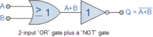

A NOR gate can be represented by an OR gate followed by a NOT operation. The small circle at the output of the OR gate is called an inversion bubble and represents logical inversion.
Transistor Logic NOR Gate
A simple two-input NOR gate can be constructed using Resistor-Transistor Logic (RTL). In this configuration, the inputs are connected to the bases of the transistors.
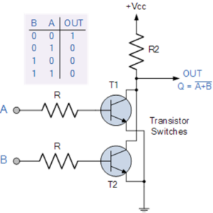

For the output Q to be logic 1, both transistors must remain OFF. If either transistor turns ON, the output is pulled toward logic 0.
The Digital Logic NOR Gate
2-Input Logic NOR Gate
A two-input NOR gate has two inputs, A and B, and one output, Q.
2-Input NOR Gate Truth Table
| A | B | Q = A + B |
|---|---|---|
| 0 | 0 | 1 |
| 0 | 1 | 0 |
| 1 | 0 | 0 |
| 1 | 1 | 0 |
Boolean Expression:
Q = A + B
The output is 1 only when both A and B are 0.
3-Input NOR Gate
A three-input NOR gate has three inputs, A, B, and C, and one output, Q.
3-Input NOR Gate Truth Table
| A | B | C | Q = A + B + C |
|---|---|---|---|
| 0 | 0 | 0 | 1 |
| 0 | 0 | 1 | 0 |
| 0 | 1 | 0 | 0 |
| 0 | 1 | 1 | 0 |
| 1 | 0 | 0 | 0 |
| 1 | 0 | 1 | 0 |
| 1 | 1 | 0 | 0 |
| 1 | 1 | 1 | 0 |
Boolean Expression:
Q = A + B + C
The output of a three-input NOR gate is 1 only when all three inputs are 0.
Multi-Input NOR Gates
Like the OR gate, the NOR function can have any number of inputs. Commercially available integrated circuits (ICs) commonly provide NOR gates with 2, 3, or 4 inputs. When more inputs are required, multiple NOR gates can be cascaded together to implement the desired logic function.
Why is a NOR Gate Called a Universal Gate?
The NOR gate is known as a Universal Gate because it can be used to construct other basic logic gates. Similar to a NAND gate, NOR gates can be interconnected in different configurations to create various logic functions. The three fundamental logic gates—AND, OR, and NOT—can be implemented using only NOR gates.
Logic Gates Using Only NOR Gates
By connecting multiple NOR gates in suitable configurations, it is possible to create several other logic gates.
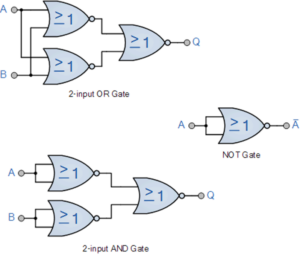

- NOT gate
- OR gate
- AND gate
- NOR gate
- Exclusive-OR (XOR) gate
- Exclusive-NOR (XNOR) gate
This universal property makes the NOR gate an important building block in digital electronics and logic circuit design.
NOR Gate Applications
NOR gates are widely used in digital electronic circuits and can be used wherever logical inversion and OR-based decision-making are required.
- Digital logic circuits
- Control circuits
- Logic gate implementations
- Combinational logic circuits
- Sequential logic circuits
- Memory and control applications
- Implementation of other logic gates
Conclusion
A NOR gate is the complementary form of an OR gate and performs an OR operation followed by logical inversion. Its output is logic 1 only when all inputs are logic 0. The NOR gate can be designed with two or more inputs and is commonly available in 2-input, 3-input, and 4-input configurations. Its ability to implement AND, OR, NOT, XOR, XNOR, and other logic functions makes it a universal logic gate. Because of its versatility, the NOR gate is an important component in digital electronics and logic circuit design.