

Introduction
Electrical and electronic systems rely on switches to direct current and control operations. While basic toggle or push-button switches only offer simple open or closed states, complex devices—such as multi-band radios, measuring equipment, and industrial motor controls—require the ability to select from multiple circuit pathways. A rotary switch is a versatile electromechanical device that solves this challenge by enabling a single central control knob to operate multiple circuits across several positions.
What is a Rotary Switch?
A rotary switch is an electromechanical switch that operates by rotating a central shaft or spindle. Turning the knob rotates an internal contact assembly, moving it across a series of stationary electrical terminals arranged in a circle. Rotary switches are commonly used as alternatives to complex arrays of push buttons or toggles because a single rotary control can manage multiple poles and throws simultaneously while taking up minimal panel space.


Working Principle of a Rotary Switch
The operating mechanism of a rotary switch centers around three main structural components: the rotor (spindle), the stationary contact terminals, and a detent mechanism.

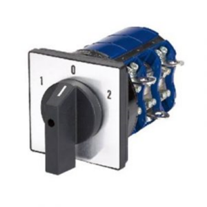

3-Position Rotary Switch
- Rotor and Spindle: A central shaft extends through the switch body. As the operator turns the outer knob, the internal spindle rotates attached conductive arms (spokes) across circular insulating plates called wafers.
- Stationary Terminals: Metal contact points are positioned around the perimeter of the wafer at precise rotational angles—most commonly spaced at 30°, 45°, 60°, or 90°. These angles dictate the total number of physical switch positions available (e.g., 360° divided by 30° allows for up to 12 distinct positions).
- Detent Spring Mechanism: Rather than spinning freely, rotary switches utilize a star-wheel or notched gear coupled with a spring-loaded ball bearing. This detent mechanism creates distinct “clicks” between positions, preventing the switch from resting halfway between contacts and causing electrical shorts or arcs.
Operators can also customize some rotary switches by inserting a mechanical stop-washer into specific internal slots, restricting a standard 12-position switch to a 4-position or 6-position setup based on circuit requirements.
Contact Arrangements: Poles and Throws
Rotary switch configurations are defined by their combination of Poles (the number of independent circuits controlled) and Throws (the number of output paths available per pole):
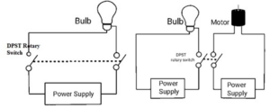

DPST Rotary Switch Circuit3-Position Rotary Switch
- 1-Pole 12-Way (SP12T): Controls 1 input circuit that can be connected to any of 12 distinct output contacts.
- 2-Pole 6-Way (DP6T): Controls 2 separate input circuits simultaneously, switching each across 6 output contacts.
- 3-Pole 4-Way (3P4T): Controls 3 independent circuits across 4 different functional positions.
- 4-Pole 3-Way (4P3T): Controls 4 distinct input lines across 3 positions.
Circuit Configurations (e.g., DPST Setup)
Consider a Double-Pole Single-Throw (DPST) rotary configuration used to control two independent electrical loads—such as an indicator lamp and an electric motor—simultaneously.
A DPST rotary switch features two input contacts and two output contacts. It effectively combines two individual SPST switching actions into a single physical turn of the spindle. When turned to the ON position, internal conductive bridges connect both inputs to their respective outputs, completing the electrical paths so that current flows to illuminate the lamp and drive the motor. Turning the switch to the OFF position breaks both circuits simultaneously, safely isolating both loads.
Advantages and Disadvantages
Advantages:
- Multi-Circuit Capacity: Manages dozens of complex circuit connections using a single control knob.
- Compact Panel Footprint: Reduces front-panel clutter by replacing multiple individual toggle or push-button switches.
- Tactile Precision: Integrated detent mechanisms deliver clear physical feedback to ensure exact contact alignment.
- Customizable Positions: Mechanical stop-washers allow quick field adjustments to limit rotational positions.
Disadvantages:
- Mechanical Wear: Physical friction between moving contacts gradually wears down conductive plating over time.
- Not Ideal for High-Speed Switching: Manual rotation is significantly slower than digital or solid-state electronic switching.
- Competition from Digital Interfaces: Modern touchscreens and microcontrollers have replaced mechanical rotary switches in many consumer electronics.
Common Applications
Rotary switches remain heavily utilized in industrial and commercial electronics where physical tactile control is essential:
- Test and Measurement Instrumentation: Serves as the primary range-selector knob on multimeters, oscilloscopes, and signal generators.
- Communication Systems: Used as channel selectors on two-way radios, aviation communication consoles, and multi-band receivers.
- Audio and Broadcast Gear: Acts as input selectors, gain step attenuators, and equalizer controls on mixing boards and high-end audio amplifiers.
- Industrial Equipment: Found on heavy machinery control panels for selecting operational modes (e.g., Manual / Off / Auto).