

Introduction
An asynchronous counter is a digital counter in which the flip-flops are not driven by the same clock signal. Instead, the output of one flip-flop is used to trigger the next flip-flop. Because the changes propagate from one stage to the next, asynchronous counters are also known as ripple counters.
An asynchronous counter with n flip-flops can have up to 2n counting states. For example, a 4-bit asynchronous counter has 16 possible states, from binary 0000 to 1111, and is therefore known as a MOD-16 counter. Asynchronous counters are particularly useful in frequency division applications. They can also be designed as truncated or MOD counters with fewer counting states than the maximum possible number.


Truncated Asynchronous Counters
A truncated asynchronous counter is created by forcing the counter to reset to zero at a predetermined count. This produces a counter with fewer states than the maximum modulus of the flip-flops. A full-sequence counter uses all of its available states, while a truncated counter uses only a selected number of states. Additional combinational logic can be connected to the flip-flop outputs to detect a particular count and asynchronously reset the counter.

Asynchronous Decade Counter
A MOD-16 asynchronous counter can be modified with additional logic gates to produce a decade counter, also known as a divide-by-10 counter. Decade counters are commonly used for standard decimal counting and arithmetic applications.
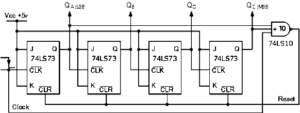

When the output count reaches decimal 10, represented by:
DCBA = 1010
the counter is asynchronously reset to zero. A counter that counts from binary 0000 (decimal 0) to 1001 (decimal 9) has ten valid states and is known as a BCD decade counter. This type of asynchronous counter counts upward from 0000 on each appropriate edge of the input clock signal until it reaches 1001, which represents decimal 9.
When the next clock pulse causes the counter to reach decimal 10, the required flip-flop outputs become logic 1. The NAND gate then changes its output state and applies the reset signal to the CLEAR (CLR) inputs of the flip-flops. As a result, all outputs are reset to 0000. The counter therefore operates as a MOD-10 or decade up-counter.
Decade Counter Truth Table
| Clock Count | QD | QC | QB | QA | Decimal Value |
|---|---|---|---|---|---|
| 1 | 0 | 0 | 0 | 0 | 0 |
| 2 | 0 | 0 | 0 | 1 | 1 |
| 3 | 0 | 0 | 1 | 0 | 2 |
| 4 | 0 | 0 | 1 | 1 | 3 |
| 5 | 0 | 1 | 0 | 0 | 4 |
| 6 | 0 | 1 | 0 | 1 | 5 |
| 7 | 0 | 1 | 1 | 0 | 6 |
| 8 | 0 | 1 | 1 | 1 | 7 |
| 9 | 1 | 0 | 0 | 0 | 8 |
| 10 | 1 | 0 | 0 | 1 | 9 |
| 11 | 0 | 0 | 0 | 0 | 0 — Counter resets |
Decade Counter Timing Diagram
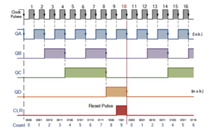

The same principle used for the decade counter can be adapted to create other counting sequences by changing the connections to the NAND gate inputs or by using different combinations of logic gates.
MOD-12 Asynchronous Counter
For example, a MOD-12 counter can be constructed by detecting the binary value 12:
12 = 1100
In this case, the appropriate outputs, such as QC and QD, can be connected to the detection logic so that the counter resets when the count reaches 12. Here, QA represents the least significant bit (LSB).
Choosing Flip-Flops for a Truncated Counter
The maximum number of states available from n flip-flops is: 2n
Therefore, when designing a truncated asynchronous counter, the number of flip-flops should be selected so that the available modulus is greater than or equal to the required modulus. For example, if a counter must count from 0 to 39 and then repeat, it requires a MOD-40 sequence. Five flip-flops provide a maximum of:
25 = 32
which is insufficient. Therefore, six flip-flops are required:
26 = 64
The counter can then be truncated to produce the required MOD-40 sequence.
Divide-by-128 Frequency Divider
To build a divide-by-128 counter, seven flip-flops are required because:
128 = 27
Using dual flip-flop ICs such as the 74LS74 may require multiple ICs to complete the circuit. Another approach is to use two TTL 7493 ripple counters. One can be configured as a divide-by-16 counter and the other as a divide-by-8 counter because:
16 × 8 = 128
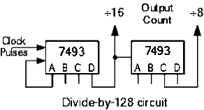

The two counters can then be cascaded to form a divide-by-128 frequency divider.
Standard Asynchronous Counter ICs
Standard asynchronous counter ICs are available for implementing different divide-by functions. For example, the 74LS90 programmable ripple counter/divider can be configured for divide-by-2, divide-by-5, or combinations of these functions. The 74LS390 is a dual-decade counter/divider IC that can provide several divide-by combinations, including divide-by-2, 4, 5, 10, 20, 25, 50, and 100.
Frequency Dividers
Because ripple counters can truncate counting sequences and produce divide-by-N outputs, they can be used as frequency dividers. A frequency divider reduces a high-frequency clock signal to a lower frequency that is more suitable for timing and digital applications.
Generating a 1 Hz Timing Signal
Suppose an accurate 1 Hz timing signal is required for a digital clock. A 555 timer configured as an astable multivibrator can generate a square-wave signal. However, the timing accuracy of a basic 555 timer circuit depends on the component values, design, and device characteristics.
A more stable approach is to generate a higher-frequency timing signal and then divide it using a multi-stage ripple counter. For example, a frequency of approximately 262.144 kHz can be divided by an appropriate binary counter to obtain a 1 Hz timing signal.
1 Hz Timing Signal from an Asynchronous Ripple Counter
This illustrates how high-frequency clock signals can be divided down to accurate lower-frequency timing signals.
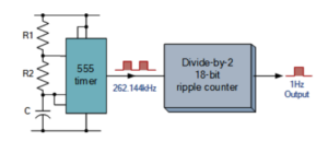

By using stable high-frequency oscillators together with multi-bit frequency dividers, precision frequency generators can be designed for applications such as:
- Digital clocks
- Watches
- Event timing
- Electronic instruments
- Electronic musical instruments
- Music synthesizers
Propagation Delay in Asynchronous Counters
One of the major disadvantages of asynchronous counters is the propagation delay between the arrival of the clock pulse and the corresponding change at the counter output. Because each flip-flop triggers the next stage, the output changes ripple through the counter one stage at a time. For this reason, an asynchronous ripple counter is sometimes called a propagation counter. In a counter with many stages, the propagation delays of individual flip-flops can accumulate, producing a significant delay between the input clock and the final output.
At high operating frequencies, this delay can cause temporary or false output states and can limit the maximum usable clock frequency. Furthermore, the outputs of the individual stages do not change simultaneously. Instead, they change sequentially, producing a domino-like effect as the signal propagates through the counter.
For this reason, asynchronous counters are generally less suitable for high-frequency counting applications involving a large number of bits. Synchronous counters address this limitation by using a common clock signal for their flip-flops.
Advantages of Asynchronous Counters
- Asynchronous counters can be constructed using toggle or D-type flip-flops.
- The flip-flops are not all driven by the same clock signal, which gives the circuit its asynchronous operation.
- Each flip-flop output controls or triggers the next stage in the counter chain.
- They are also known as ripple counters because the change in state ripples from one flip-flop to the next.
- They can be used to build divide-by-N counter circuits.
- Truncated asynchronous counters can be designed to produce different modulus values.
Disadvantages of Asynchronous Counters
- Additional re-synchronizing circuitry may be required in some applications.
- Extra feedback logic is required for truncated counting sequences that do not use all available states.
- With a large number of bits, the cumulative propagation delay can become significant.
- Because of their propagation delay, they are sometimes referred to as propagation counters.
- At high clock frequencies, temporary invalid states can lead to counting errors or glitches.
- The sequential clocking of the stages makes asynchronous counters slower than comparable synchronous counters.
Conclusion
An asynchronous counter is a digital counter in which the flip-flops are triggered sequentially rather than by a common clock signal. This operating principle makes it simple to construct ripple counters and frequency dividers. By using additional logic, asynchronous counters can be truncated to create MOD-10 decade counters, MOD-12 counters, MOD-40 counters, and other custom counting sequences.
They are useful in frequency division, timing circuits, digital clocks, event counters, and other digital applications. However, propagation delay limits their use at high clock frequencies, especially when many flip-flop stages are connected together.