
Introduction
Frequency division is the process of reducing the frequency of an input clock signal by a specific division factor. Flip-flops and binary counters are commonly used to divide an input frequency into lower-frequency signals.
Frequency Division Using a Divide-by-2 Counter

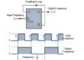
The waveform above shows that feeding the output of a flip-flop back to its input can produce an output signal at half the frequency of the input clock. Therefore, the circuit performs frequency division by 2, meaning that the output frequency is one-half of the input clock frequency:
fout = fin / 2
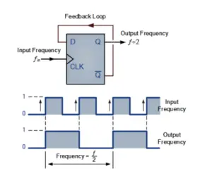
This type of circuit can be used as the basic building block of a ripple counter. In a ripple counter, the clock pulse triggers the first flip-flop, whose output then triggers the next flip-flop. This process continues through the chain, producing a ripple effect in the timing signals.
The Toggle Flip-Flop
The T-type or Toggle flip-flop is another digital circuit that can be used for frequency division. A T flip-flop can be created by modifying a standard JK flip-flop or by configuring a D-type flip-flop appropriately. A toggle flip-flop changes, or toggles, its output state whenever it receives the appropriate clock transition. This makes it particularly useful for frequency division and binary counter applications.
74LS73 Toggle Flip-Flop
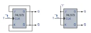
The name toggle flip-flop comes from its ability to switch between its two output states. A T-type flip-flop has two possible output states, HIGH and LOW, making it suitable for divide-by-2 frequency division.
Frequency Division Using Toggle Flip-Flops
Binary ripple counters can be constructed by connecting the output of one toggle flip-flop to the clock input of the next flip-flop. Since a toggle flip-flop changes state on each appropriate clock transition, each stage divides the frequency by 2. If two T-type flip-flops are connected in series:
First flip-flop: fout = fin / 2
Second flip-flop: fout = fin / 4
Therefore, two flip-flops produce an output frequency that is one-quarter of the original input frequency. Similarly, adding another toggle flip-flop divides the frequency by 2 again. For n flip-flops connected in a binary frequency divider:
fout = fin / 2n
For example:
- 1 flip-flop → Divide-by-2
- 2 flip-flops → Divide-by-4
- 3 flip-flops → Divide-by-8
- 4 flip-flops → Divide-by-16
- 5 flip-flops → Divide-by-32
Asynchronous 3-Bit Binary Counter
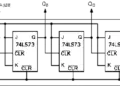
A chain of toggle flip-flops can also operate as an asynchronous 3-bit binary counter. The outputs QA, QB, and QC represent a binary count from 0 to 7. In an asynchronous counter, the clock is applied only to the first flip-flop. The output of the first flip-flop provides the clocking signal for the next stage, and the output of the second stage clocks the third stage. Therefore, each stage effectively divides the frequency of the signal by 2.
This configuration is called asynchronous because the flip-flops do not all change state at exactly the same time. The clocking event propagates from one stage to the next. The counter shown is an up-counter because it counts from 0 to 7 in increasing order. Asynchronous down-counters can also be designed to count in the opposite direction.
Truth Table for a 3-Bit Asynchronous Up Counter
| Clock Cycle | QC | QB | QA | Decimal Value |
|---|---|---|---|---|
| 0 | 0 | 0 | 0 | 0 |
| 1 | 0 | 0 | 1 | 1 |
| 2 | 0 | 1 | 0 | 2 |
| 3 | 0 | 1 | 1 | 3 |
| 4 | 1 | 0 | 0 | 4 |
| 5 | 1 | 0 | 1 | 5 |
| 6 | 1 | 1 | 0 | 6 |
| 7 | 1 | 1 | 1 | 7 |
Frequency Division with D-Type or Toggle Flip-Flops
A D-type flip-flop configured to toggle its state can also be used as a divide-by-2 frequency divider. Its output frequency is half of the input frequency. By connecting additional D-type or toggle flip-flops, divide-by-2, divide-by-4, divide-by-8, and other power-of-two frequency dividers can be constructed. Thus, a chain of flip-flops can act as both a frequency divider and a binary counter.
Frequency Division Using Binary Counters
A counter can be considered a specialized register or pattern generator that produces a sequence of binary output states in response to an input clock signal. In digital applications, counters can increment or decrement their count in response to clock pulses. When configured as frequency dividers, they can also reduce the frequency of the input clock signal.
Counter Modulus
Multiple flip-flops can be connected, or cascaded, to form a binary counter. The number of different states through which the counter passes before returning to zero is called its modulus (MOD). For a binary counter containing n flip-flops, the maximum number of states is:
MOD = 2n
For example, a counter with three flip-flops has:
23 = 8 states
It counts from decimal 0 to 7 and is therefore called a MOD-8 counter.
Similarly, a four-bit binary counter has:
24 = 16 states
It counts from 0 to 15 and is called a MOD-16 counter.
Examples of Binary Counter Modulus
| Number of Flip-Flops | Maximum States | Counter Type |
|---|---|---|
| 1 | 21 = 2 | MOD-2 |
| 2 | 22 = 4 | MOD-4 |
| 3 | 23 = 8 | MOD-8 |
| 4 | 24 = 16 | MOD-16 |
| 8 | 28 = 256 | MOD-256 |
Adding more flip-flops increases the available modulus. Multiple counter stages can also be cascaded to obtain higher modulus counters.
Ripple Counters
In a multi-bit asynchronous counter, the change of state propagates from the least significant bit (LSB) toward the most significant bit (MSB). This produces a ripple-like effect through the counter. For this reason, multi-bit asynchronous counters are commonly known as ripple counters or ripple dividers. Standard integrated circuits are available for implementing ripple counters. Examples include the 74LS393 dual 4-bit counter and the 74HC4060, which combines a ripple counter with an oscillator section for frequency division applications.
Frequency Division Summary
A chain of toggle-mode flip-flops can be used as a divide-by-2 frequency divider. One flip-flop divides the input clock frequency by 2, while two flip-flops divide it by 4. In general, an n-stage binary divider provides:
fout = fin / 2n
One useful characteristic of an ideal toggle flip-flop frequency divider is that its output can have an approximately 50% duty cycle when operated under suitable conditions.
Divide-by-N Counters
The output frequency of a counter used as a frequency divider is determined by its modulus:
fout = fin / MOD
Such circuits are commonly called divide-by-N counters. Counters are constructed by connecting individual flip-flops and can be classified according to how their clock inputs are driven.
Asynchronous Counters
In an asynchronous, or ripple, counter, the first flip-flop is driven by the external clock. Each subsequent flip-flop receives its clock signal from the output of the preceding flip-flop.
Synchronous Counters
In a synchronous counter, the clock input is connected to all flip-flops. Therefore, all flip-flops receive the clock signal at the same time, although their outputs may still depend on the combinational logic controlling their inputs.
Conclusion
Frequency division is an important application of flip-flops and binary counters. A toggle flip-flop can divide an input frequency by 2, while multiple cascaded flip-flops can provide divide-by-4, divide-by-8, divide-by-16, and other power-of-two frequency divisions.
Asynchronous ripple counters are particularly useful for simple frequency division and counting applications. The number of flip-flops determines the maximum binary modulus, while the counter’s configuration determines the actual division factor. Understanding divide-by-2 counters, toggle flip-flops, counter modulus, and ripple counters provides the foundation for designing frequency dividers and digital timing circuits.