

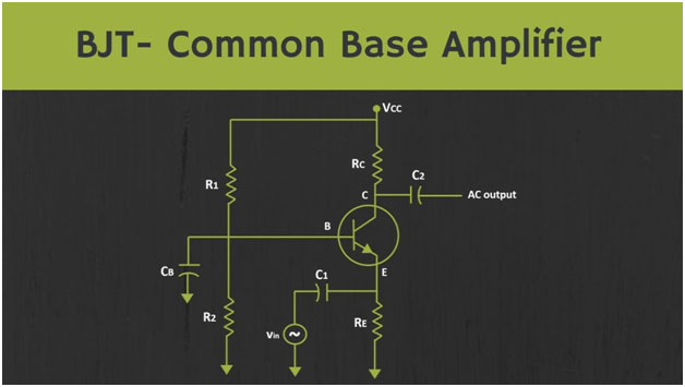

The AC input signal is applied at the emitter terminal, while the output is measured at the collector terminal. And for a moment, let’s assume that some DC biasing voltage is already applied at the base terminal. So, for the AC signals, this DC voltage sources will act as a zero. That means now, this base terminal will act as AC ground. That means now if you see, the input signal is applied between the emitter and the ground terminal or effectively between the emitter and the base terminal. Similarly, the output is measured between the collector terminals or effectively between the collector and the base terminal. That means in this configuration, the base terminal is common between the input and the output side and that is why this amplifier is known as the common base amplifier. Now normally when we connect the input signal, then we apply it through the coupling capacitor because through the coupling capacitor can isolate the AC and DC signals. So if we connect the input signal a shown in the figure. So we apply the input signal in this fashion, when we know that for the DC signals, these coupling capacitors will act as an open circuit so because of that there won’t be any path for the biasing current. Because here, the emitter terminal will act as an open circuit. So because of that, there won’t be any bias current and there won’t be any output signal. That means there has to have some path for the biasing current, so let’s provide the path for the biasing current and let’s connect the input signal in this fashion. Now, in this circuit, although there is a path for the DC biasing current, but for the AC signal this coupling capacitor will act as a short circuit and because of that, here the input signal will also get grounded and due to that, we will not get any output signal. So it shows that, if we want to couple the input signal, then there has to have some series resistor at the emitter terminal. So this is the proper way to couple the input signal at the emitter terminal. Now so far we have assumed that there is some biasing voltage that is already applied at the base terminal. But now let’s see how to bias this base terminal so far biasing we can apply some fixed biasing voltage via this base resistor we can use voltage divider bias.
