


Proper Measurement Techniques Using an Oscilloscope Probe
Before attempting to measure ripple or transient, some background on probing with an oscilloscope should be discussed. As the magnitude of the signal of interest tends to be measured in millivolts, any internal signal that is amplified or external signal that gets picked up can easily obscure or distort the signal and lead to incorrect results. It is extremely important to mitigate this through proper probe measurement techniques.
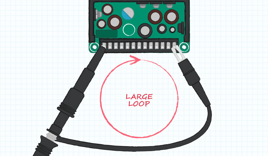
The most important thing that the tester can do to ensure a good measurement is to minimize the ground loop created by the probe. The loop created by the probe’s return path causes an inductance which can amplify internal noise and pick up external noise. Probes typically come with an alligator style ground clip, similar to that shown in the image below. While simple to connect, these ground clips lead to large ground loops which are not recommended for these measurements. Instead, there are two common and preferred methods for achieving a small ground loop: the “tip and barrel” method and the “paperclip” method.

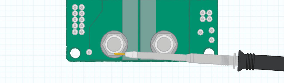
The tip and barrel method removes the ground cover and probe clip leaving the tip and barrel of the probe exposed. The tip of the probe is then applied to the output voltage and the barrel is angled such that it contacts ground at a point very close to the tip. A drawback of this method is that the accessible probe points, or points at which you can apply both tip and barrel, may not be ideal and/or be at a distance from any output capacitor. Ideally, the probe should be placed as close to the output capacitor as possible.

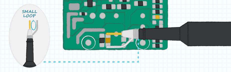
On the other hand, the paperclip method takes the tip and barrel method and adds a small coil of wire with a short lead to the barrel. This creates a tweezer-like tip to the probe, allowing for a more flexible probe location, while maintaining a small loop area.

Although these are not the only methods to acquire a good signal, efforts should be made to keep the ground loop as small as possible regardless of the chosen method.
Ripple and Noise
Ripple is the inherent ac component of the output voltage caused by the internal switching of the power supply. Noise is the manifestation of parasitics within the power supply that appear as high frequency voltage spikes on the output voltage. Datasheets specify a maximum peak-to-peak deviation of the output voltage caused by the ripple and noise. As discussed above, it is important to use good probing methods to ensure that the measurement accurately represents the ripple and noise of the power supply.
When testing ripple and noise there are a few conditions to remember. First, the loading has a significant impact on the ripple, therefore, it is important that the measurement is taken under the same loading conditions, typically full load, as specified on the datasheet. The input voltage also affects the ripple and the test should be performed at all input voltages of interest. In addition to the electrical conditions, many manufacturers specify some external capacitors (it is typical to have an electrolytic on the order of 10 µF and a ceramic of 0.1 µF) which are applied to the output of the power supply for the purposes of the measurement. The probe should be placed close to these capacitors. Lastly, it is typical to specify a 20 MHz bandwidth limit on the oscilloscope channel for this measurement.
In general, only one scope probe is required to perform this test, with the probe placed across an output capacitor or a specified external capacitor using the probe measurement methods discussed above.
Transient Response
Transient response is the amount that the output voltage may deviate due to a change in loading. When the load changes, the power supply cannot immediately react to the new conditions and either has too much stored energy or not enough. The excess energy or lack of energy will be the responsibility of the output capacitors. They will either expend their charge to sustain the load causing a decrease in voltage, or they will store the excess energy causing an increase in voltage. Over several switching cycles the power supply will adjust to store only the energy that the load needs, while the output voltage will return to its nominal value. When measuring the transient response, the amount that the output voltage deviates from its nominal value, the time it takes to recover, or the time that the voltage falls outside of the specified regulation limits are all of interest.
Unlike ripple and noise, whose conditions are limited to loading and input voltage, transient response has a few additional conditions which may affect its measurement. Important conditions to note are the slew rate of the applied load step, the starting current, and the ending current. The slew rate has a large effect on the transient response because the faster the load changes the more the output will deviate before the power supply can catch up to the changing conditions. The beginning and ending current levels can have an impact as well. Power supplies often behave differently at light loads and a transient that crosses between these regions may cause the power supply to react differently than if the transient occurred in a single region. The start and end currents, along with slew rate, also determine the time that the current is changing and should match the specified conditions.
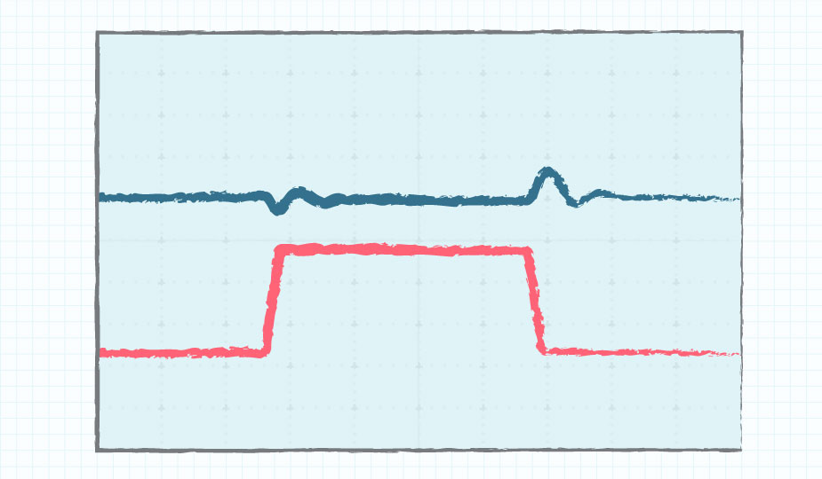
To make the transient response measurement, the user will need two scope channels. The first probe should be across the output of the power supply close to the output pins or regulation point. Measuring the output voltage away from the regulation point will cause a dc offset between the two loading states caused by voltage drop in the output cabling. The second probe should be of the current or a signal that is synchronous to the transient load change. This probe will be used as a trigger so that the resulting output voltage deviation may be seen clearly.
Conclusion
Ripple and transient are a common part of power supply evaluation. When measuring these characteristics with an oscilloscope it is important that the probe loop area be minimized to avoid distortion of the signals in question. In addition to proper probe measurement techniques, the conditions under which the datasheet specifies these measurements must also be known and adhered to for any comparison to be valid.