

By Mark Patrick, Mouser Electronics
In-wheel drivetrains are starting to be applied in electric vehicle (EV) programmes because of the space-saving benefits they achieve. However, eliminating the differential and driveshafts presents a few technical challenges, the major one being the reduction of unsprung weight. This article looks at the history and development of in-wheel motors and runs through some design integration issues.
The general layout of the power architecture of an EV is pretty much the same as a conventional internal combustion engine (ICE) vehicle. Auto designers have tended to ‘play it safe’, sticking to the traditional layout of the gearbox, differential, or driveshafts, by just replacing the petrol or diesel engine with an electric motor. However, at the turn of the 20th century, someone came up with a better idea.

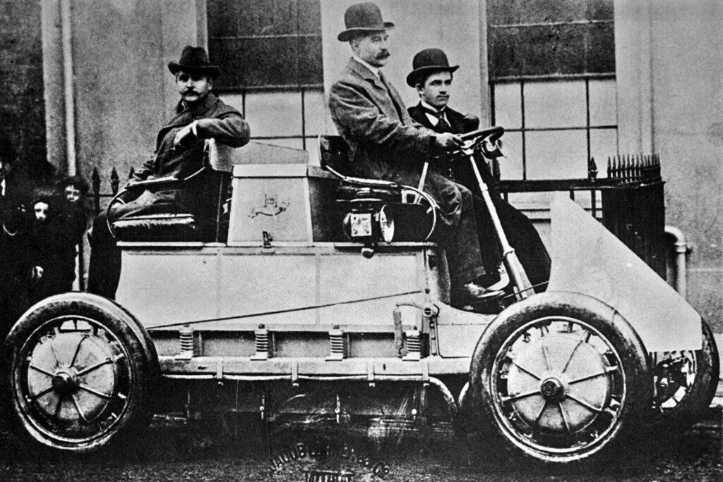
In 1901, automotive engineer and founder of Porsche, Ferdinand Porsche introduced the Lohner-Porsche Electromobile. The hybrid vehicle was powered by an ICE-driven generator, which drove electric motors embedded in each wheel hub. Control ofeach motor was basic, but the architecture eliminated the power losses in the conventional powertrain and gearbox. Although the design was innovative, it soon slipped into the annals of time as the steering was stiff, horsepower was low and, because it weighed about a ton-and-a-half, its range was poor.

More recently, however, the idea of putting electric motors in the wheels is being revisited. In the early 1970s, the battery-powered Lunar Roving Vehicles (LRVs) used an electric motor to drive each wheel. Sometimes referred to as ‘active wheel’ technology, Michelin was a pioneer of this technique over a decade ago [1]. Active development continues with the recent Nissan’ BladeGlider’ [2] concept car, demonstrating its practical reality.

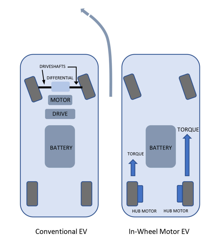
There are real advantages of driving the wheels directly as opposed to a single chassis-mounted unit. Firstly, in-wheel motors eliminate all the associated drivetrain losses from a centralised motor, and with no mechanical differentials, the overall weight of the can be lower. One company active in in-wheel motor development claims that depending on battery size and driving style, the reduced weight and energy savings can improve range by more than 30% [3].

Another benefit of locating motors in the wheel’s hub is that the vehicle cabin space can potentially be much larger and more flexible. If the drive electronics are also integrated into the hub, the wiring harness is much simpler. Having the variable frequency drive within the wheelwill reduce electromagnetic emissions from the cables.
Improvement of driving dynamics and safety is another significant advantage. Each hub motor can be controlled for torque, target wheels speed and braking, reacting to driver inputs, and wheel sensor readings. Known as ‘torque vectoring’, each wheel is powered separately for optimum handling and safety (Figure 2). Although in-wheel motors can achieve a braking effect, conventional hydraulic or friction brakes are still necessary to prevent overloading the drive unit during heavy braking and emergency stops.
However, with all these benefits, there are a few drawbacks to placing the motor inside the wheel. The obvious one is the added cost of using multiple motors, each with its electronic drive, instead of a single motor for the same power output.One could argue that the energy savings will eventually give a return on investment, and the other safety and performance advantages will also have an offsetting value.
There are other practical downsides; putting weight below the vehicle’s suspension system adds to its ‘unsprung mass’ – the enemy of handling. However, according to tests, the effect is not disruptive under normal driving conditions up to certain weight limits. Also, locating the motor and drive in the wheel is a more severe environment than a single motor within the chassiswhich is protected from vibration.
Harsh conditions
Road shocks, and other vibrations, are perhaps the worst environment for an electric motor. Added to this are road debris and corrosive elements, such as rainwater and road salt. Also, friction brakes can get very hot, and the motor and drive, although very efficient, also generate heat. For long life and reliability, therefore, the motor and its components must be robust. Of course, automotive quality standards apply; the ISO 26262 for functional safety and systems must achieve the Automotive Safety Integrity Level (ASIL) D, which is the highest category. Each component must also be certified appropriately from automotive-qualified suppliers meeting ISO/TS 16949 quality standards with a Production Part Approval Process (PPAP). Here, the AEC-Qxx standard applies to all passive and active electronic components.
Electronic controllers
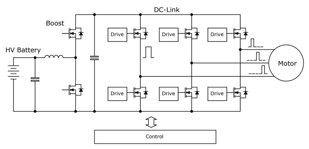
Although today’s motors are small and powerful, the drive electronics add to size and weight when embedded in the wheel hub. The permanent magnet, synchronous motors (PMSM) used for traction require a three-phase variable frequency drive; this is implemented using a ‘bridge’ of semiconductor switches under pulse width modulation (PWM) control. At high frequency, the bridge is switched with an output effective amplitude set by the pulse width, representing torque demand (Figure 3).
Although EV designs predominantly use IGBTs as the switches, engineers are starting to adopt new semiconductor technologies that offer faster switching and control and EMI benefits. There is also an increase in efficiency and, consequently, a reduction in size and weight. Silicon carbide (SiC) MOSFETs, for example, feature low conduction losses, have high operating temperatures, and switch extremely quickly, allowing PWM frequencies in the region of tens of kHz.
One of the features of motor control bridge circuits is a commutation, that is, during switch ‘dead’ time and regeneration, current flows in the reverse direction. A fast diode has to be added to the IGBTs in parallel to allow the current to flow back. A benefit of using SiC MOSFETs is that an integral ‘body’ diode can perform this function; however, for the highest efficiency, and external diode can be added instead.
The highest proposed in-wheel power level is currently around 80kW, for which SiC MOSFETs are available in appropriate voltage and current ratings. In comparison, the power level for a single chassis mounted motor is hundreds of kW, as it has to supply the full vehicle power. Choosing between IGBTs and SiC MOSFETs is not entirely clear-cut, with automotive-grade IGBTs being more widely available at the highest current ratings.
A wide range of automotive-grade IGBTs, SiC MOSFETs, and other active devices from manufacturers including Infineon, STMicroelectronics, Texas Instruments, and Wolfspeed Creeis available from Mouser Electronics, along with a large portfolio of passive and electromechanical parts.
Conclusion
The heritage of in-wheel electric motors is long and distinguished. Advances in motor and drive technology are enabling it to become a viable alternative to the chassis-mounted motor. With this comes the benefits of better fuel economy, range, and driving experience. The move towards autonomous vehicles will marry well with the potential for large cabin space, making the vehicle more of a room to relax or work in.
References
[1] https://www.greencarcongress.com/2008/12/michelin-to-com.html
[2] https://www.nissan-global.com/EN/ZEROEMISSION/HISTORY/BLADEGLIDER/
[3] https://www.proteanelectric.com/