Working principle:

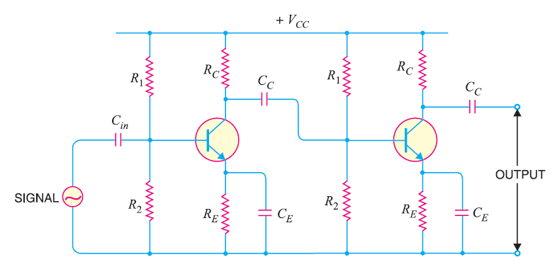
The circuit diagram of two stage RC coupled CE amplifier is shown in above figure. When the input AC signal is applied to the input of the first stage, it is amplified by BJT Q1 and appears across the collector load RC. This signal is applied to the input of the second stage through a capacitor CC. The second stage further amplifies this signal. In this way, the cascaded stages amplify the AC signal and the overall gain is equal to the product of the individual stages gains.
It will be interesting to know that the overall voltage gain will be less than the product of the gains of individual stages. It is because when a second stage is made to follow the first stage, the effective load resistance of the first stage is reduced due to the shunting effect of the input resistance of second stage. This reduces the gain of the stage which is loaded by the next stage.
For instance, the gain of first and second stage will be reduced due to loading effect of next stage. The overall voltage gain shall be equal to the product of the voltage gains of two stages. The output signal if a two stage RC coupled CE amplifier is in phase with the input signal. It is because of the fact that its phase has been reversed twice by the amplifier.