Introduction
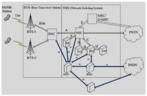
In a 2G GSM network, communication between different components is made possible through a set of well-defined interfaces. These interfaces connect elements such as mobile stations, base stations, and switching systems, enabling seamless communication and data exchange.
List of GSM Network Interfaces
The GSM system defines several interfaces, each serving a specific function:
Um Interface
The Um interface is the radio interface between the Mobile Equipment (ME) and the Base Transceiver Station (BTS). It is used for wireless communication. A modified version of ISDN LAPD, known as LAPDm, is used for signaling.
Abis Interface
The Abis interface connects the Base Station Controller (BSC) and BTS. It is an internal interface within the Base Station Subsystem (BSS) and is responsible for radio equipment control and frequency allocation.
A Interface
The A interface connects the BSS to the Mobile Switching Center (MSC). It is responsible for transmitting data required for channel allocation, time slot management, and handover operations.
B Interface
The B interface connects the MSC and the Visitor Location Register (VLR). It uses the MAP/B protocol and is mainly used internally to access subscriber information.
C Interface
The C interface connects the Home Location Register (HLR) to the Gateway MSC (GMSC) or SMS Gateway. It uses the MAP/C protocol to obtain routing information for incoming calls from external networks.
D Interface
The D interface connects the VLR and HLR. It exchanges subscriber location and management information using the MAP/D protocol.
E Interface
The E interface connects two MSCs. It is used for inter-MSC communication and supports handover operations using the MAP/E protocol.
F Interface
The F interface connects the MSC and Equipment Identity Register (EIR). It verifies the status of the device IMEI using the MAP/F protocol.
H Interface
The H interface connects the MSC and the SMS Gateway. It is used to transfer SMS messages using the MAP/H protocol.
I Interface
The I interface connects the MSC and the Mobile Equipment (ME). Messages are transparently transmitted through the Base Station Subsystem (BSS).
Importance of GSM Interfaces
Although not all interfaces were strictly standardized, they provided sufficient definitions to ensure interoperability and proper functioning of GSM network components. The GSM air interface (Um interface) was carefully designed to optimize performance, reduce costs, and improve battery efficiency in mobile devices.
Features of GSM Air Interface
- Efficient communication between mobile and base station
- Reduced hardware complexity in mobile devices
- Improved battery life due to efficient power usage
- Time-slot based transmission eliminating the need for duplexers
GSM Signal and GMSK Modulation
The GSM system uses Gaussian Minimum Shift Keying (GMSK), a type of phase shift keying modulation.
Why GMSK is Used in GSM
- High resistance to noise
- Low interference outside the assigned bandwidth
- Constant power output for efficient RF amplifier operation
- Reduced battery consumption in mobile devices
The GSM signal operates within a bandwidth of 200 kHz, which is also the channel spacing.
Data Transmission in GSM
A single GSM carrier is divided into eight time slots, allowing multiple users to share the same frequency.
- Total data rate per carrier: ~270 kbps
- Effective data rate per time slot: ~24.8 kbps
- Voice data rate (after encoding): ~13 kbps
Error correction techniques are used to handle issues such as interference, fading, and transmission errors.
Conclusion
GSM network interfaces play a vital role in enabling communication between various network components. Interfaces such as Um, Abis, and A ensure smooth interaction between mobile devices and network infrastructure. Combined with efficient modulation techniques like GMSK, GSM provides reliable communication, efficient bandwidth usage, and improved battery performance, making it one of the most successful mobile communication technologies.