• Home
  • About Us
  • Contact Us
Semiconductor for You
  • Home
  • Semiconductor News
  • Technology
    • Automotive
    • Consumer Electronics
    • IoT
    • Lighting
    • Power Management
    • Wireless
    • Personal Electronics
    • Hardware & Software
    • Research
    • Medical Electronics
    • Embedded Design
    • Aerospace & Defence
    • Artificial Intelligence
  • DIY Projects
  • Market
  • Industries
    • Renesas Electronics
  • Knowledge Base
  • Events
  • Tools
    • Resistor Color Code Calculator
No Result
View All Result
Semiconductor for You
No Result
View All Result
Home Knowledge Base

2N5551 Transistor : Pin Configurations & Its Applications

Bhushan Chaudhary by Bhushan Chaudhary
August 16, 2022
in Knowledge Base
0
ADVERTISEMENT
  • The 2N5551 is a silicon NPN bipolar junction high-voltage transistor designed for general-purpose applications like amplification and switching.
  • When the collector current is 10mA, the amplification factor (have) is 80. It also has excellent shifting characteristics, allowing it to amplify low-level signals.
2N5551 NPN Transistor
  • Now we should know what is a NPN transistor and how it works which will make it easy for us to understand how and where we can use the 2N5551 transistor in practical applications.
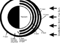
  • NPN transistors are those that have one p-type material sandwiched between two n-type materials. The NPN transistor amplifies the weak signal that enters the base and generates high-amplitude signals at the collector end.
Basic NPN transistor construction and working
  • In an NPN transistor, an electron moves from the emitter to the collector region, causing current to flow through the transistor. This type of transistor is commonly used in circuits because its majority charge carriers are electrons, which have higher mobility than holes.
  • A small voltage VBE is observed when the emitter-base junction is forward biassed. VCE is the reverse bias voltage. The majority of charge carriers in the emitter are repelled towards the base due to the forward bias. Because the base is lightly doped, electron-hole recombination is very low in the base region. The majority of electrons enter the collector region.
  • When the emitter is forward biassed, electrons flow towards the base, producing the emitter current IE. The majority of the charge carriers in the P-type material combine with the holes here.
  • Because the NPN transistor’s base is lightly doped, only a few electrons can combine, and the remaining current is known as the base current IB. When the collector region is skewed in the opposite direction, it exerts a greater force on electrons approaching the collector junction, attracting electrons at the collector.

Features and Specifications

  • Collector to the emitter breakdown voltage of 160V.
  • Collector to emitter saturation voltage of 200mV at a 50mA collector current.
  • Power dissipation of 625mW.
  • DC collector current of 600mA.
  • DC gain of 30 at Ic=50mA.
  • Operating junction temperature range from -55°C to 150°C.

Pin Configurations

  • The 2N5551 comes in a TO-92 package and has three terminals.
  • The pin diagram of the 2N5551 transistor is shown below.
Pin Configuration : 2N5551 Transistor
    1. Emitter- Current Drains out through emitter, normally connected to ground.
    2. Base- Controls the biasing of the transistor, Used to turn ON or OFF the transistor.
    3. Collector-Current flows in through collector, normally connected to load.

Applications of 2N5551 Transistor

  • The transistor is commonly used to boost audio or other low-power signals.
  • Low power amplifiers.
  • Current amplifiers.
  • Small signal boosters.
  • Audio or other signal amplifiers.
  • Darlington pair
Content Protection by DMCA.com
Bhushan Chaudhary

Bhushan Chaudhary

Browse by Category

  • Aerospace and Defence
  • Articles
  • Automotive
  • Consumer-Electronics
  • Hardware & Software
  • Interview
  • IoT
  • Knowledge Base
  • Lighting
  • Market
  • personal-electronics
  • Power Management
  • Research
  • Semiconductor Events
  • Semiconductor News
  • Technology
  • Wireless
Semiconductor for You

Semiconductor For You is a resource hub for electronics engineers and industrialist. With its blend of
technology features, news and new product information, Semiconductor For You keeps designers and
managers up to date with the fastest moving industry in the world.

Follow Us

Browse by Category

  • Aerospace and Defence
  • Articles
  • Automotive
  • Consumer-Electronics
  • Hardware & Software
  • Interview
  • IoT
  • Knowledge Base
  • Lighting
  • Market
  • personal-electronics
  • Power Management
  • Research
  • Semiconductor Events
  • Semiconductor News
  • Technology
  • Wireless

Recent News

TME, DC power connectors from Amphenol GEC

TME, DC power connectors from Amphenol GEC

June 27, 2025
Analog Semiconductors Poised to Cross USD 100 Billion by 2032

Analog Semiconductors Poised to Cross USD 100 Billion by 2032

June 26, 2025
  • About
  • Advertise
  • Privacy & Policy
  • Contact

© 2022 Semiconductor For You

No Result
View All Result
  • Home
  • Semiconductor News
  • Technology
    • IoT
    • Wireless
    • Power Management
    • Automotive
    • Hardware & Software
  • Market
  • Knowledge Base
  • Tools
    • Resistor Color Code Calculator

© 2022 Semiconductor For You