
Introduction
The 555 Timer IC was invented in 1971 at Signetics Corporation by Hans Camenzind. It was originally released as the SE555 or NE555. Compared to other ICs such as operational amplifiers, the 555 timer is inexpensive, reliable, and compact.
This IC is widely used in digital logic probes, DC–DC converters, tachometers, analog frequency meters, voltage regulators, and temperature-controlled devices. It can operate as an astable or monostable multivibrator, making it suitable for timers, delays, pulse generators, oscillators, and more. The SE555 functions between –55°C to 125°C, while the NE555 operates between 0°C to 70°C.
Block Diagram & Working
The internal structure of a 555 timer includes a voltage divider, two comparators, a flip-flop, and an output stage.
- The voltage divider is made of three 5k resistors that generate two reference voltages: one-third and two-thirds of the supply voltage (5V to 15V).
- The comparators compare input voltages. If the voltage at the + terminal exceeds the – terminal, the comparator outputs “1,” and vice versa.
- The first comparator compares the threshold pin with 2/3 Vcc, while the second compares the trigger pin with 1/3 Vcc.
- The outputs of these comparators control the Set and Reset inputs of the flip-flop.
- The flip-flop output drives the output pin and also controls a transistor that discharges the external timing capacitor through the discharge pin.
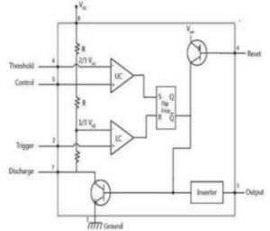
The external Reset pin can override other inputs and reset the timer at any moment.
555 Timer Pin Configuration
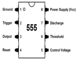
The 555 timer is packaged in an 8-pin Dual Inline Package (DIP). Each pin serves a unique function:
| Pin No. | Pin Name | Function |
|---|---|---|
| 1 | Ground | Connects the IC to ground. |
| 2 | Trigger | An active-low input that starts the timing cycle when voltage falls below 1/3 Vcc. |
| 3 | Output | Provides a digital output that switches between low (0V) and high (near Vcc). Used to drive loads such as LEDs. |
| 4 | Reset | Active-low input that resets the timer. Usually tied to Vcc if not used. |
| 5 | Control Voltage | Allows external control of threshold voltage. Usually bypassed to ground with a 0.01µF capacitor. |
| 6 | Threshold | Monitors capacitor voltage. When it reaches 2/3 Vcc, the timing cycle ends and output goes LOW. |
| 7 | Discharge | Discharges timing capacitor through an internal transistor. Used with resistors and capacitors to set timing. |
| 8 | Vcc | Power supply input (4.5V to 15V). |
Different Modes of the 555 Timer
The 555 timer can operate in three modes based on how external resistors and capacitors are connected:
- Monostable Mode: Generates a single pulse when triggered.
- Astable Mode: Produces a continuous square-wave output.
- Bistable Mode: Acts as a flip-flop with two stable states.
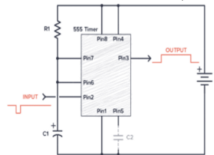
1. Monostable Mode
Monostable mode has one stable state and one unstable state. When a trigger pulse is applied, the output changes state for a fixed time period and then returns to its stable state automatically.
Timing Interval Formula
The pulse width is determined by:
T = 1.1 × R1 × C1
Example: With R1 = 1MΩ and C1 = 1µF:
T = 1.1 × 1,000,000 × 0.000001 = 1.1 seconds
RC Component Selection
- Select C1 first (capacitor values are limited compared to resistor values).
- Calculate R1 based on the required timing interval using:R1 = T / (1.1 × C1)
- Avoid electrolytic capacitors due to tolerances and leakage.
- Use timing resistors between 1kΩ and 1MΩ.
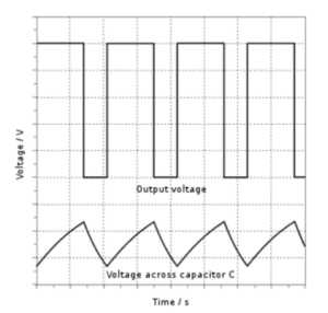
2. Astable Mode
In astable mode, the 555 timer produces a free-running square wave. There is no stable state; the output continuously switches between high and low.
Timing Formulas
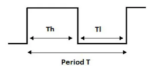
The output high time (Th), low time (Tl), and total period (T) are:
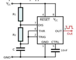
Th = 0.7 × (R1 + R2) × C1
Tl = 0.7 × R2 × C1
T = Th + Tl = 0.7 × (R1 + 2R2) × C1
Frequency:
f = 1 / T = 1.44 / [(R1 + 2R2) × C1]
This mode is mainly used for blinking LEDs, clock pulses, tone generation, and oscillator circuits.
3. Bistable Mode
Also known as the Schmitt Trigger mode, bistable mode has two stable states: HIGH and LOW. The output changes only when the Trigger or Reset pins receive a LOW pulse.
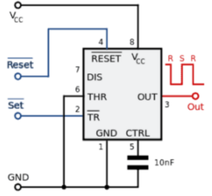
- A LOW on Trigger pin → Output becomes HIGH.
- A LOW on Reset pin → Output becomes LOW.

This mode is used in push-button latches, toggle switches, and flip-flop circuits.
Applications of 555 Timer IC
- Pulse generation and waveform shaping
- Time delay and sequential timing circuits
- Astable and monostable multivibrators
- PWM and PPM circuits
- Tachometers and temperature sensors
- DC voltage regulators
- Voltage-to-frequency converters
- Frequency dividers
- Pulse detectors
- Timer switch and automation circuits