

- We can use RC circuits to not only charge but also discharge capacitors. Assume we connect a battery to an electric circuit that also includes an uncharged capacitor and a resistor. The capacitor will begin to charge once the battery is connected. Assume that after the capacitor has been fully charged, we disconnect the battery from the electric circuit. The capacitor will begin to discharge, and electrons will travel from the lower potential plate to the capacitor’s higher potential plate, creating an electric current.
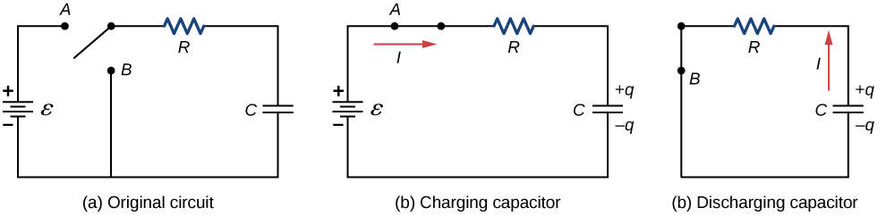
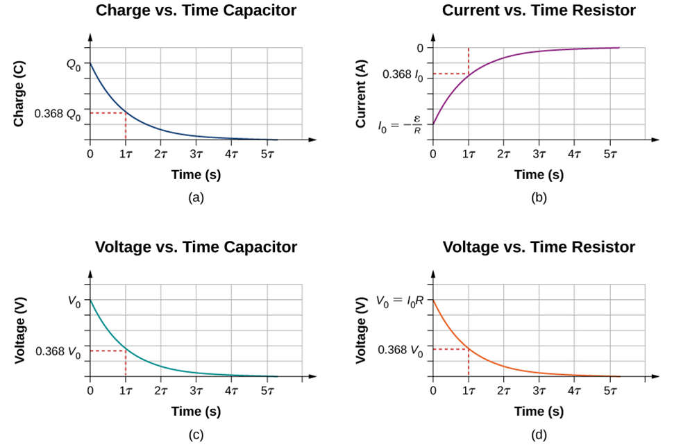
- When the switch in Figure (a) is moved to position B, the circuit is reduced to part (c), and the charged capacitor is allowed to discharge through the resistor. Figure (a) depicts a graph of the charge on the capacitor as a function of time. When using Kirchhoff’s loop rule to analyze the circuit as the capacitor discharges, the equation VRVC=0 is obtained, which simplifies to IR+qC=0. Using the current definition dqdtR=qC and integrating the loop equation, we get the following equation for the charge on the capacitor as a function of time.
- Here, Q is the initial charge on the capacitor, and =RC is the circuit’s time constant. The charge decreases exponentially from the initial charge, approaching zero as the time approaches infinity, as shown in the graph. Taking the time derivative of the charge yields the current as a function of time:I(t)=−QR/Ce−t/τ.
RC Combination in Relaxation Oscillator
- The diagram below depicts a very simple relaxation oscillator circuit that operates on the basic charge-discharge theory of a capacitor.
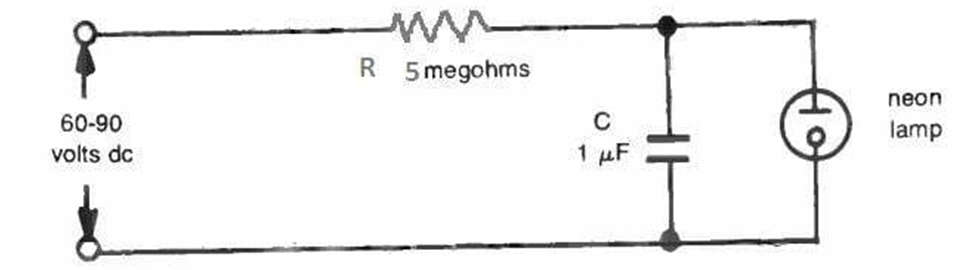
- It consists of a resistor (R) and a capacitor (C) connected in series to a dc voltage source. A neon lamp is used in parallel with the capacitor to allow physical inspection of the circuit’s operation.
- The lamp behaves almost like an open circuit until the voltage reaches its threshold voltage limit, at which point it instantly switches ON and conducts current like a conductor, beginning to glow. As a result, the supply voltage for this current must be greater than the neon triggering voltage.
Working of RC Discharging Circuit
- When the circuit is turned on, the capacitor slowly begins to charge according to the RC time constant. The lamp begins to receive a rising voltage generated across the capacitor.
- When the charge across the capacitor reaches a value close to or equal to the neon lamp’s firing voltage, the neon lamp conducts and begins to illuminate.
- When this occurs, the neon opens a discharge path for the capacitor, and the capacitor begins to discharge. This causes a drop in the voltage across the neon, and when this level falls below the firing voltage of the neon, the lamp turns off and shuts down.
- The process is now repeated, causing the neon to flash ON/OFF. The flashing rate or frequency is determined by the RC time constant value, which can be adjusted to enable either slow or fast flashing.
- The time constant for the circuit T = 5 (megohms) x 0.1 (microfarads) = 0.5 seconds if the component values are as shown in the diagram.
- This means that by adjusting the RC values, the flashing rate of the neon can be adjusted to suit individual preferences.