

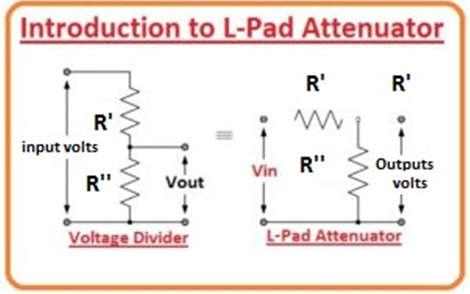
- An L pad is a network made up of two impedances that, when drawn on a schematic, resemble the letter capital “L.” It is commonly used for impedance matching and attenuation.
- The L-pad attenuator circuit is equivalent to the voltage divider circuitry used to reduce the input voltage by some amount.
- The two resistors are connected in series across the completion of the input voltage in the diagram, while the output is obtained across only one resistance.
- This circuit contains two resistors that form an overturned letter “L,” hence the name “L-pad Attenuators.” Attenuation is specified as Vout/Vin for this type of circuitry.
- In the circuit shown, input resistor R1 is connected in series with the output, while resistor R2 is connected in parallel with the load.
- This “L” formed prearrangement’s output voltage is separated by a factor equal to the proportion of these two resistor values.
- (Vout = Vin multiplied by Volts)
- Because the L-pad attenuator is prepared with resistors, no phase change occurs in this attenuator.
- The addition of the attenuator between the supply and the load does not change the input voltage, so the resistance obtained by the supply should remain constant at all times.
- Because the two resistors have constant standards, if the load’s impedance is not infinite, the attenuation is.
- As a result, the L-pad attenuator can only source an impedance tie in one way.
- L-pad attenuators are commonly used in audio submissions to reduce a higher or higher power signal while comparing the impedance between the source and load to deliver high power transfer.
- However, if the supply impedance differs from the load impedance, the L-pad attenuator can be completed to connect either impedance but not both.
- This is because the resistor configurations do not produce a similar impedance when viewed from both sides of the system.
- Because the L-pad attenuator is irregular, another category of attenuators, such as the regular T configuration or the “Pi-pad” attenuator, can be used to join two inadequate impedances in both directions.
Impedance Matching With L-Pad Attenuator
- As long as the source and load impedances are primarily resistive, a resistor-based L-pad can be used to match the source and load impedances. If the source or load impedance contains capacitive or inductive elements, the complex part of the impedance can be matched using an L configuration of the capacitor and inductor.
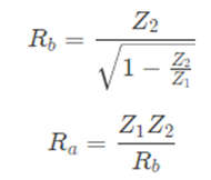
- When performing impedance matching with an L-pad, the Z1 side of the L-pad always faces the side (either source or load) with higher impedance.
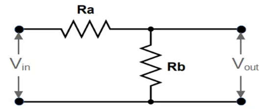
- The resistor values Ra and Rb in this configuration can be calculated using the following formulas:
Voltage Divider vs. L-Pad Attenuator
- The L-pad attenuator has some design constraints that a voltage divider does not:
- Potentiometers (rheostats) must be used instead of standard resistors in the L-pad.
- The resistance values of the two potentiometers must be linked to maintaining the same total impedance. When one resistance rises, the other falls, and vice versa.
L-pad Attenuator Features
- The L-pad attenuator is a passive circuit and decently resistors system that can be used to reduce the power of a signal when the input supply and load impedances are identical.
- In acoustic electronics, L-pad attenuators are typically used to reduce the auditory signal produced by an amplifier and sent to a loudspeaker or earphones.
- However, because the “L-pad attenuator” is a persistent impedance device, at low power levels, the attenuator converts all of the energy not directed to the load into temperature, which can be significant.
- Other enhanced attenuator enterprises are used at extremely high frequencies or where an attenuator circuit is required to effortlessly connect the input and output.
Applications of L-pad Attenuator
- In broadcasting stations, attenuators are used to control the volume.
- Attenuators are used in laboratories to obtain smaller voltage signals for testing purposes.
- Fixed attenuators are used in circuits to improve impedance matching.
- These are used to safeguard circuits against damage caused by high voltage values.
- In measuring RF signals, RF attenuators are used for power dissipation protection.
- Optical attenuators are used in fiber optic communication to match the levels of the transmitter and receiver.