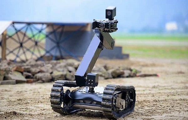
This project presents a hybrid surveillance system that combines a two-wheel drive (2WD) land vehicle with a quadcopter drone for integrated land and aerial monitoring. Designed for engineering students, the project aims to provide a cost-effective, functional prototype suitable for real-time surveillance applications in security, agriculture, and disaster zones.

Introduction
With the growing demand for intelligent surveillance systems, this project explores a dual-mode robotic system capable of navigating on land and flying in the air. Such systems provide broader surveillance coverage, flexibility, and adaptability in dynamic environments.
Objectives
- Develop a mobile robotic platform with both land and aerial capabilities.
- Integrate live video feed systems for real-time monitoring.
- Enable remote wireless control using commonly available modules.
- Include basic automation such as obstacle avoidance and path following
Components Required
Land Vehicle Section:
- 2 x DC Geared Motors (12V, 300 RPM)
- 2 x Wheels + 1 Caster Wheel
- Motor Driver (L298N or L293D)
- Arduino Uno / Raspberry Pi
- Ultrasonic Sensor (HC-SR04)
- Chassis (Acrylic/Metal/3D-Printed)
- Bluetooth or Wi-Fi Module (e.g., HC-05 or ESP8266)
- 12V Li-ion Battery or 3S Li-Po Battery
Drone Section:
- 4 x Brushless Motors (A2212)
- 4 x ESCs (Electronic Speed Controllers)
- 4 x Propellers
- Quadcopter Frame
- Flight Controller (KK2.1.5 / APM / Pixhawk)
- MPU6050 Gyroscope/Accelerometer
- FPV Camera or ESP32-CAM
- Drone Battery (3S Li-Po)
Common Components:
- Voltage Regulators (7805 / LM317)
- GPS Module (optional)
- Jumper Wires, Breadboard, Switches
Methodology
Land Vehicle:
- Controlled via Arduino Uno.
- Motors driven using L298N driver.
- Ultrasonic sensor for obstacle detection.
- Commands received via Bluetooth or Wi-Fi.
Drone Section:
- Controlled via dedicated drone controller.
- Stability managed by MPU6050 and flight controller.
- FPV camera streams live video.
Switching Between Modes:
- Manual switch or software-based toggle to alternate between land and air operations.
- Power circuits are isolated using relays or MOSFETs to prevent interference.
Circuit Diagrams
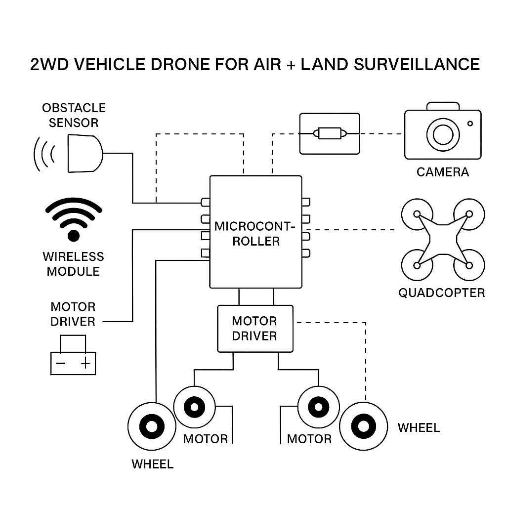
- Block Diagram: Illustrates communication flow between land system, drone, and control unit.
- 2WD Motor Driver Circuit: Shows connection of motors, driver IC, Arduino, and power source.
- Drone Motor Connection: Displays ESCs wired to flight controller and battery.
- Ultrasonic Sensor Wiring: Demonstrates interfacing with Arduino for obstacle detection.
Results
Vehicle moves forward, backward, turns left/right via remote commands.
- Drone launches from ground platform and hovers/stabilizes in air.
- Live video feed is viewable on mobile/PC.
- Obstacle avoidance functional on ground.
Applications:
- Military base and border patrol
- Agricultural crop monitoring
- Disaster zone search and rescue
- Factory or industrial perimeter inspection
Advantages:
- Extended surveillance coverage with dual mobility
- Energy-efficient ground mode
- Cost-effective and modular design
- Easy to customize and upgrade
Conclusion
This 2WD Vehicle Drone project showcases how basic embedded systems, motor controls, and sensor integration can be combined into an innovative, dual-mode surveillance platform. The project enhances student understanding of electronics, control systems, wireless communication, and robotics—preparing them for real-world automation challenges.
Future Work
- Implement AI-based video processing
- Autonomous drone docking and charging
- Solar panel integration for energy sustainability
- Real-time location mapping via GPS and IoT platforms
Code Snippets
Arduino Code for 2WD Movement with Obstacle Avoidance:
#define ENA 9
#define IN1 8
#define IN2 7
#define trigPin 10
#define echoPin 11
void setup() {
pinMode(ENA, OUTPUT);
pinMode(IN1, OUTPUT);
pinMode(IN2, OUTPUT);
pinMode(trigPin, OUTPUT);
pinMode(echoPin, INPUT);
Serial.begin(9600);
}
void loop() {
long duration, distance;
digitalWrite(trigPin, LOW);
delayMicroseconds(2);
digitalWrite(trigPin, HIGH);
delayMicroseconds(10);
digitalWrite(trigPin, LOW);
duration = pulseIn(echoPin, HIGH);
distance = duration * 0.034 / 2;
if (distance < 20) {
digitalWrite(IN1, LOW);
digitalWrite(IN2, LOW);
} else {
digitalWrite(IN1, HIGH);
digitalWrite(IN2, LOW);
}
}
Drone Setup:
- Calibrate ESCs
- Mount MPU6050 and connect to flight controller
- Bind transmitter/receiver
- Configure flight modes using Mission Planner or KK2 display
- Check motor rotation and propeller direction before flight