• Home
  • About Us
  • Contact Us
Semiconductor for You
"
  • Home
  • Semiconductor News
  • Technology
    • Automotive
    • Consumer Electronics
    • IoT
    • Lighting
    • Power Management
    • Wireless
    • Personal Electronics
    • Hardware & Software
    • Research
    • Medical Electronics
    • Embedded Design
    • Aerospace & Defence
    • Artificial Intelligence
  • DIY Projects
  • Market
  • Industries
    • Renesas Electronics
  • Knowledge Base
  • Events
  • Tools
    • Resistor Color Code Calculator
No Result
View All Result
Semiconductor for You
No Result
View All Result
Home Articles

What are the triggering modes of TRIAC?

Semiconductor For You by Semiconductor For You
May 28, 2021
in Articles
0
ADVERTISEMENT

There are the triggering modes of TRIAC (Triode for alternating current) are given below.

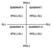
  • I +mode: The ‘I’ indicates first quadrant operation. The MT2 (main terminal 2) positive with respect to MT1 (main terminal 1). The ‘+’ symbol shows the polarity of gate (G) with respect to MT1 (main terminal 1). In this mode the conduction of current takes place from MT2 to MT1.
  • I –mode: The ‘-’ shows the polarity of gate (G) with respect to MT1 (main terminal 1). The conduction of current takes place from MT2 to MT1.
  • III +mode: The ‘III’ indicates the third quadrant operation where MT1 (main terminal 1) is positive with respect to MT2 (main terminal 2). The ‘+’ symbol shows the polarity of gate with respect to MT1 (main terminal 1). The conduction of current takes place from MT1 to MT2.
  • III –mode: The ‘-’ symbol shows the polarity of gate (G) with respect to MT1 (main terminal 1). The conduction of current takes place from MT1 to MT1­.
Triggering modes of TRIAC
Content Protection by DMCA.com
Semiconductor For You

Semiconductor For You

Browse by Category

  • Aerospace and Defence
  • Articles
  • Automotive
  • Consumer-Electronics
  • Hardware & Software
  • Interview
  • IoT
  • Knowledge Base
  • Lighting
  • Market
  • personal-electronics
  • Power Management
  • Research
  • Semiconductor Events
  • Semiconductor News
  • Technology
  • Wireless
Semiconductor for You

Semiconductor For You is a resource hub for electronics engineers and industrialist. With its blend of
technology features, news and new product information, Semiconductor For You keeps designers and
managers up to date with the fastest moving industry in the world.

Follow Us

Browse by Category

  • Aerospace and Defence
  • Articles
  • Automotive
  • Consumer-Electronics
  • Hardware & Software
  • Interview
  • IoT
  • Knowledge Base
  • Lighting
  • Market
  • personal-electronics
  • Power Management
  • Research
  • Semiconductor Events
  • Semiconductor News
  • Technology
  • Wireless

Recent News

Infineon SEMPER™ NOR Flash memory family achieves ASIL-D functional safety certification

Infineon SEMPER™ NOR Flash memory family achieves ASIL-D functional safety certification

May 9, 2025
onsemi’s AR0145CS Hyperlux SG Image Sensors, Now at Mouser

onsemi’s AR0145CS Hyperlux SG Image Sensors, Now at Mouser

May 8, 2025
  • About
  • Advertise
  • Privacy & Policy
  • Contact

© 2022 Semiconductor For You

No Result
View All Result
  • Home
  • Semiconductor News
  • Technology
    • IoT
    • Wireless
    • Power Management
    • Automotive
    • Hardware & Software
  • Market
  • Knowledge Base
  • Tools
    • Resistor Color Code Calculator

© 2022 Semiconductor For You