Introduction
The Colpitts Oscillator is an LC oscillator that produces sinusoidal oscillations using a capacitive voltage divider as its feedback network. Its basic design is similar to that of the Hartley Oscillator, except that the feedback is obtained from a capacitive divider rather than an inductive tap.
Basic Concept
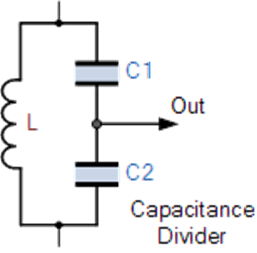
In the Colpitts Oscillator, two capacitors C1 and C2 are connected in series across a single inductor L. Together, these components form the tuned tank circuit. The junction between C1 and C2 serves as the feedback point.
The condition for sustained oscillations is the same as in a Hartley oscillator and is given by:
XC1 + XC2 = XL
This capacitive configuration reduces both self and mutual inductance effects within the tank circuit, thereby improving the frequency stability and simplifying the design.
Colpitts Oscillator Circuit Description
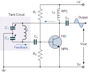
In the basic Colpitts oscillator circuit, the junction of capacitors C1 and C2 (connected in series) acts as a voltage divider and is connected to the emitter terminal of the transistor. When the power supply is switched on, capacitors C1 and C2 charge and discharge through the inductor L, generating oscillations.
These oscillations are applied across the base-emitter junction, amplified by the transistor, and appear at the collector as the output. The resistors R1 and R2 provide DC biasing and stabilization for the transistor, while coupling capacitors act as DC blocking elements.
A radio-frequency choke (RFC) is often used in the collector circuit to offer high reactance at the oscillation frequency and low resistance at DC, aiding the start-up of oscillations.
Working Principle
Positive feedback is essential for sustained undamped oscillations. In the Colpitts oscillator, this is achieved through the capacitive divider formed by C1 and C2. The ratio of these two capacitors determines the feedback level.
Typically, C1 and C2 are “ganged” together—meaning they vary simultaneously—to maintain a constant feedback ratio during tuning.
Frequency of Oscillation
The frequency of oscillation of a Colpitts oscillator depends on the resonant frequency of the LC tank circuit and is given by:
f = 1 / (2π√(L × CT))
where the total capacitance CT of capacitors C1 and C2 connected in series is:
1 / CT = (1 / C1) + (1 / C2)
Phase Shift and Feedback
The transistor amplifier operates in a common emitter configuration, introducing a 180° phase shift between input and output signals. Since the voltage divider (C1 and C2) also provides a 180° phase shift, the total phase shift around the loop is 360°, satisfying the Barkhausen criterion for sustained oscillations.
Feedback Fraction
The voltage across C1 represents the oscillator’s output voltage (Vout), while the voltage across C2 represents the feedback voltage. Hence, the feedback fraction is determined by the ratio of C1 to C2:
Feedback Fraction = C1 / C2
A small feedback value may prevent oscillation, while excessive feedback can distort the waveform. Therefore, selecting appropriate C1 and C2 values is critical to maintaining a pure sinusoidal output.
Advantages of Colpitts Oscillator
- High frequency stability due to the capacitive feedback network.
- Simple and compact design.
- Produces a pure sinusoidal waveform.
- Suitable for high-frequency applications (RF oscillators, signal generators).
Conclusion
The Colpitts Oscillator is a widely used and reliable LC oscillator that employs a capacitive voltage divider to generate stable sinusoidal signals. By adjusting the capacitance ratio and inductance, it can operate across a broad frequency range, making it ideal for use in RF circuits, transmitters, and function generators.