What is Over Voltage Protection?
Over-voltage protection is a power supply feature that shuts down or clamps the output if the voltage exceeds a predetermined level. It is used to protect electronic components from damage due to excessive voltage levels.
Most power supplies employ an over-voltage protection circuit to safeguard components from failures caused by internal faults or external factors such as distribution line disturbances. The effects of over-voltage vary — ranging from component degradation to complete malfunction or even fire hazards.

When designing effective protection, both the magnitude and duration of the over-voltage must be considered. The protection system typically sets a threshold voltage above which the control circuit either shuts down the supply or diverts excess voltage to other parts of the circuit, such as a capacitor.
Aspects of Analog Power Supply Failure
In many analog regulated power supplies, the series pass transistor can fail, resulting in a short circuit between the collector and emitter. When this happens, the full unregulated voltage appears at the output, which can be 1.5 to 2 times the intended output voltage.
Such an occurrence would expose the entire system to unacceptably high voltage, potentially damaging multiple integrated circuits and components. For example, a typical power supply may deliver 5V stabilized power to logic circuits, with an input voltage of around 10V to 15V for stabilization and ripple rejection. Even 10V could destroy modern chips, making over-voltage protection critical.
Crowbar Circuit Diagram
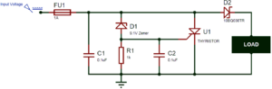
The crowbar circuit is simple, cost-effective, and easy to build, making it an ideal solution for quick protection. The input voltage is the monitored voltage, and the circuit is designed to cut off the supply if the voltage exceeds a certain limit — for example, 9.1V.
Crowbar Circuit Operation
When the input voltage exceeds the threshold, the crowbar circuit creates a short circuit across the power lines, blowing the fuse and disconnecting the power supply from the load. This prevents damage caused by high voltage. The operation is similar to a crowbar being dropped across power lines — hence the name.
The over-voltage threshold is determined by the Zener diode value. The circuit includes an SCR (Silicon Controlled Rectifier) connected across the input voltage and ground. Normally, the SCR remains off as its gate is grounded. When the voltage exceeds the Zener breakdown voltage, the diode conducts, sending current to the SCR’s gate, which then short-circuits the supply and blows the fuse.
For instance, in a circuit using a 9.1V Zener diode, if the input voltage rises above 9.1V, the Zener conducts, triggering the SCR. The SCR then creates a short between the input and ground, causing the fuse to blow due to high current flow, thereby isolating the load from damage.
Key Components and Their Functions
- Fuse: Essential for protection. Its rating should be lower than the SCR’s maximum current rating but higher than the normal load current. Ensure the power supply can deliver enough current to blow the fuse during a fault.
- 0.1µF Capacitor: Acts as a filter to remove voltage spikes and noise, preventing false triggering of the circuit.
- 9.1V Zener Diode: Determines the over-voltage limit. The circuit triggers when voltage exceeds 9.1V. The designer can adjust this value based on system requirements.
- 1KΩ Resistor: A pull-down resistor that keeps the SCR’s gate grounded and off until the Zener begins to conduct.
- 47nF Capacitor: Used as a snubber to suppress voltage spikes during switching, preventing false triggering. Its value should be optimized to balance filtering and response time.
- Thyristor (SCR): Responsible for short-circuiting the supply rails. It must handle high current without damage. Its gate voltage should be lower than the Zener breakdown voltage.
- Schottky Diode: Optional but provides reverse current protection. It prevents backflow from the load side. A Schottky diode is preferred due to its low forward voltage drop.
Crowbar Circuit Limitations
Although this over-voltage protection circuit is reliable and commonly used, it has certain limitations that should be considered:
- The trigger voltage in a thyristor-based design depends on the Zener diode and is usually not adjustable. Selecting the correct Zener voltage is therefore critical. The trigger voltage should be slightly higher than the supply voltage to avoid false activation due to noise or voltage spikes.
- When the power supply is used in RF designs (e.g., transmitters), proper power line filtering is necessary before and after the transmitter to prevent interference.
- During over-voltage events, the circuit blows the fuse to protect the load. Therefore, the fuse must be replaced each time the protection circuit is triggered.
Conclusion
The SCR-based crowbar circuit provides a simple, low-cost, and highly effective method for over-voltage protection in power supply systems. Despite its few limitations, it remains a vital safeguard for sensitive electronic circuits, ensuring long-term reliability and protection against sudden voltage surges.