Introduction
A Solid State Relay (SSR) is an electronic switching device that turns on or off when an external AC or DC voltage is applied across its control terminals. SSRs perform the same switching function as electromechanical relays (EMRs) but have no moving parts, resulting in a significantly longer operational lifetime.
An SSR consists of three main parts: a sensor that responds to the input control signal, an electronic switching device that controls the load, and a coupling mechanism that isolates and transfers the signal without mechanical movement. SSRs can be designed to switch both AC and DC loads.

Power semiconductor devices such as thyristors, triacs, transistors, MOSFETs, and IGBTs are used in SSRs to switch
currents ranging from milliamps to several hundred amperes. Compared to electromechanical relays, SSRs offer faster switching, no contact wear, and high reliability. However, they cannot handle large momentary overloads and typically exhibit higher ON-state resistance.
Solid State Relay Input
An opto-isolator (optocoupler) is a key component inside an SSR. It consists of an infrared LED and a photosensitive device, such as a phototransistor or phototriac, housed in a single package. When current passes through the LED, it emits light that activates the photosensitive device on the output side. Because the input and output sections are linked only through light, SSRs provide very high electrical isolation (typically several thousand volts).
Opto-isolators allow SSRs to interface easily with digital control circuits and microcontrollers, and they can also
transmit low-frequency or DC signals. In some designs, optical fibres may be used for complete electrical isolation.
Structure of Solid State Relays
A typical SSR has four terminals—two for input control and two for output load. Regardless of type, all SSRs consist of the following three sections:
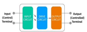
- Input Circuit (Control Circuit)
- Drive Circuit
- Output Circuit (Load Circuit)
1. Input Circuit
The input circuit receives the control signal and converts it into a trigger for the SSR. Based on input voltage type,
input circuits may be:
- DC input circuit
- AC input circuit
- AC/DC input circuit
Types of DC Input Circuits
• Resistive Input Circuit
Input current increases linearly with input voltage. Suitable when the control voltage is constant.
• Constant Current Input Circuit
Once a threshold is reached, input current remains constant even if voltage increases. This is useful when the control voltage varies widely (e.g., 3–32V). Input circuits may also support logic compatibility including TTL, CMOS, and HTL. When using PWM control, AC SSRs should operate below 10 Hz due to switching limitations.
2. Drive Circuit
The drive circuit transfers the input signal to the output stage. It may include:
- Isolation coupling circuit
- Functional circuits (rectifier, zero-cross circuit, protection circuits, etc.)
- Trigger circuit
Isolation Methods
• Optocoupler Isolation
Uses LED–phototransistor, LED–triac, or LED–photodiode arrays to achieve complete isolation between control and load.
• High-Frequency Transformer Isolation
The input signal is converted into a high-frequency oscillation and transferred to the output side through a transformer.
3. Output Circuit
The output circuit switches the load on and off based on the trigger signal. Components commonly used include:
- MOSFETs (for DC loads)
- IGBTs
- Thyristors / SCRs
- Triacs (for AC loads)
Output circuits are classified as:
- DC Output
- AC Output
- AC/DC Output
Operation of Solid State Relays
DC Load Operation
SSR DC versions usually use one or more MOSFETs. Since a single MOSFET cannot block current in both directions, AC SSRs use two MOSFETs connected back-to-back to enable bi-directional current blocking.
AC Load Operation
AC SSRs using SCRs or triacs turn off automatically at the AC zero-cross point. This prevents high-voltage transients caused by sudden current interruption and reduces electrical stress. Zero-cross SSRs switch ON only when the AC waveform is near zero, reducing inrush current and interference.
Features of Solid State Relays
- No mechanical contacts—purely semiconductor switching
- High-speed signal transfer using optocouplers
- High isolation between input and output
- No physical wear and tear
- Silent operation without electrical arcing
Advantages
- No moving parts or mechanical contacts
- Extremely long operational life (up to 109 operations)
- Highly shock and vibration resistant
- No contact bounce or arcing
- High isolation voltage
- Compatible with logic control circuits such as PLCs
- Fast switching (microseconds)
- No electrical noise and immune to electromagnetic interference
- Low control power requirement
- Compact size and multiple mounting options (PCB, panel, socket)
Disadvantages
- Higher ON-state resistance and voltage drop
- Limited switching configurations (mostly SPST)
- More expensive compared to mechanical relays
- Off-state leakage current may affect sensitive loads
- Typically dedicated for either AC or DC loads, not both
- Cannot switch low-level signals (e.g., audio)
- Specifications can be complex due to semiconductor behaviour
- Susceptible to insulation deterioration under condensation