Introduction
The great mathematician Carl Friedrich Gauss was also a pioneer in the study of magnetic fields. In 1833, he developed one of the earliest magnetic field measuring instruments known as the magnetometer, commonly referred to as the Gauss meter. He also introduced a system of units for measuring magnetism. In the CGS system, the unit of magnetic flux density is the gauss, whereas in the SI system, the unit is the tesla. One tesla is equal to 10,000 gauss.
What is a Gauss Meter?
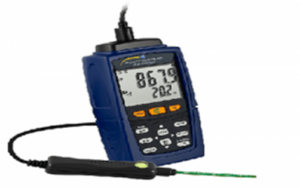

A Gauss meter is a measuring instrument used to measure the strength and direction of a magnetic field at a particular point in space. It is also used to determine the magnetization of magnetic materials such as ferromagnets. A Gauss meter mainly consists of a Hall probe, a meter, and a connecting cable. The operation of a Gauss meter is based on the Hall Effect. This instrument is capable of measuring even very small magnetic fields.
Hall Effect Principle
When an electric current flows through a conductor or semiconductor placed in a magnetic field that is perpendicular to the current, a transverse voltage is developed across the material. This phenomenon is known as the Hall Effect. The generated voltage is proportional to the strength of the magnetic field and can be measured to determine the magnetic flux density.
How Does a Gauss Meter Work?
The most important component of a Gauss meter is the Hall probe. This probe is used to measure transverse magnetic fields. Cylindrical or axial probes are used to measure magnetic fields that are parallel to the probe axis,
such as the magnetic field inside a solenoid. Flat or transverse probes are essential for measuring magnetic fields in open spaces, small air gaps, and near permanent magnets. Gauss meter probes are highly sensitive and are often protected with brass housing to withstand harsh environmental conditions. The probe allows a test current to pass through a conductor, and due to the Hall Effect, a voltage is generated. This voltage is measured and displayed by the Gauss meter. When the magnetic field changes, the meter detects the voltage variation and records the highest value to indicate the magnetic field strength.
Circuit Diagram of Gauss Meter
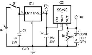
A simple and low-cost Gauss meter circuit can be designed using a Hall Effect sensor. This circuit is mainly used to measure magnetic field strength. The circuit consists of a 9 V battery, a voltage regulator (LM1117-5.0), a toggle switch, an SS49E Hall Effect sensor, and a two-pin connector for connecting a digital voltmeter (DVM) or digital multimeter (DMM).
SS49E Hall Effect Sensor
Pin Configuration
- Pin 1 (Vdd): Power supply pin
- Pin 2 (GND): Ground pin
- Pin 3 (Output): Output voltage pin
Characteristics
- Operating voltage range: 3.0 V to 6.5 V
- Package type: TO-92
- Response time: 3 microseconds
- Supply current: 4.2 mA to 8.0 mA
- Output current: 1.0 mA to 1.5 mA
- Minimum output voltage: 0.86 V
- Maximum output voltage: 4.21 V
- Quiescent output voltage: 2.25 V to 2.75 V
- Sensitivity: 1.6 to 2.0 mV/G
Circuit Working
When switch S1 is closed, a regulated voltage of 5 V is available at test point TP1. The voltage at test point TP2 depends on the position of the magnet relative to the Hall Effect sensor. A voltage regulator is used to supply a stable DC voltage to the sensor, ensuring consistent readings throughout the battery life. To measure the magnetic field, the magnet is moved close to the Hall Effect sensor, and the digital voltmeter is connected across the two-pin connector. The output voltage changes depending on the magnetic field strength and polarity.
If the voltage reading is maximum, the sensor is facing the south pole of the magnet. If the voltage reading is minimum, the sensor is facing the north pole of the magnet.
Magnetic Field Calculation
The magnetic flux density can be calculated using the following formula:
Magnetic Flux Density (B) = 1000 × (V1 − V2) / k (Gauss)
Where:
- V1 = Output voltage without the magnet near the sensor
- V2 = Output voltage with the magnet near the sensor
- k = Sensor sensitivity (mV/G)
Advantages of Gauss Meter
- Portable and compact
- Easy to operate
- Highly sensitive to weak magnetic fields
Disadvantages of Gauss Meter
- Relatively expensive
- Measurement accuracy varies with manufacturer
- Limited precision in low-cost models
Applications of Gauss Meter
- Measurement of direction and strength of weak magnetic fields
- Non-destructive testing of relays, coils, and magnetic switches
- Testing magnetic fields in AC and DC motors
- Loudspeakers and magnetic circuits testing
- Detection of electromagnetic interference on electronic equipment
- Measurement of existing magnetic fields in laboratories and industries