Introduction
In a parallel resistor network, there are multiple paths available for current flow. Because the current can divide and flow through more than one branch, resistors connected in parallel are often referred to as current dividers.


In parallel circuits, the supply current does not necessarily flow equally through every branch, as each path may have a different resistance. However, an important characteristic of a parallel resistive network is that the voltage across each resistor is the same.
Thus, all resistors connected in parallel share a common voltage. A parallel circuit is defined as one in which the resistors are connected between the same two points (or nodes) and are supplied by the same voltage source.
Resistors in Parallel
When resistors are connected such that one terminal of each resistor is connected to a common point and the other terminal is connected to another common point, they are said to be connected in parallel.
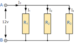
In a parallel resistor network, the voltage across resistor R1 is equal to the voltage across resistor R2, which is equal to the voltage across resistor R3, and so on. This voltage is equal to the supply voltage.
![]()
V = VR1 = VR2 = VR3
Parallel Resistor Circuit
In a typical parallel circuit, resistors R1, R2, and R3 are connected between two common points, usually labeled A and B. Each resistor provides a separate path for current flow.
Equivalent Resistance of Resistors in Parallel
Unlike series circuits, where resistances are added directly, the equivalent resistance of resistors connected in parallel is calculated by adding the reciprocals of the individual resistances.
Formula:
1 / RT = 1 / R1 + 1 / R2 + 1 / R3 + … + 1 / Rn
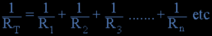
The equivalent resistance RT is obtained by taking the reciprocal of the total.
Special Case: Equal Parallel Resistors
If all resistors connected in parallel have the same value, the total resistance is simply the value of one resistor divided by the number of resistors.
For example:
- Two equal resistors: RT = R / 2
- Three equal resistors: RT = R / 3
- n equal resistors: RT = R / n
As more resistors are added in parallel, the total resistance always decreases and is always less than the smallest resistance in the network.
Conductance in Parallel Circuits
Parallel resistance is often analyzed using conductance, which is the reciprocal of resistance. Conductance is represented by the symbol G and is measured in Siemens (S).
G = 1 / R
In parallel circuits, conductance’s add directly:
GT = G1 + G2 + G3 + … + Gn
To find the total resistance from conductance, the reciprocal of the total conductance is taken:
RT = 1 / GT
Key Characteristics of Parallel Resistor Circuits
- Same voltage across all resistors
- Current divides among multiple paths
- Total resistance decreases as more resistors are added
- Total resistance is always less than the smallest resistor
Conclusion
Resistors connected in parallel provide multiple paths for current flow while maintaining a common voltage across each branch. Understanding parallel resistance and conductance is essential for analyzing electrical and electronic circuits, particularly in current divider and power distribution applications.