
Introduction
Before understanding a sampling oscilloscope, it is important to know the basic operation of a standard oscilloscope. An oscilloscope is an electronic instrument that displays electrical signals on a screen. A CRO (Cathode Ray Oscilloscope) is a common example of a conventional oscilloscope. However, CROs have limited operating bandwidth. At very high frequencies, the brightness of the display decreases, making it difficult to trace the waveform accurately. To overcome this limitation and properly trace extremely high-frequency signals, a special technique called sampling is used. This leads to the development of the sampling oscilloscope.
What is a Sampling Oscilloscope?
A sampling oscilloscope is an advanced type of digital oscilloscope that reconstructs a waveform by collecting multiple samples of an electrical signal over successive cycles.
This oscilloscope uses the stroboscopic sampling method to analyze very fast electrical signals. Small portions of the signal are sampled from different cycles and combined to form a complete waveform on the display. A waveform can be reconstructed using thousands of sample points. These samples are then amplified using a low-bandwidth amplifier before being displayed.
Sampling oscilloscopes are mainly used to detect extremely high-frequency signals, typically up to 50 GHz. Even with a low-bandwidth amplifier, very high-frequency signals can be analyzed due to the sampling process.
Sampling Method for Signal Tracing
In the sampling method, individual sample points are taken from successive cycles of a repetitive signal. Each sample corresponds to a slightly different time position in the waveform. When these samples are combined, a complete representation of the signal is obtained. This technique allows accurate analysis of high-frequency signals using relatively slow electronic circuits.
Sampling Oscilloscope Block Diagram
The input signal is applied to a sampling gate. When a sampling pulse is applied, the gate opens briefly and captures a small portion of the input signal. Sampling must be synchronized with the input signal frequency. The sampled signal is held and passed to the vertical amplifier, which amplifies it before sending it to the vertical deflection plates.
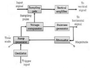
A trigger signal activates an oscillator that generates a linear ramp voltage. This ramp signal is applied to a voltage comparator along with a staircase signal. When both signals reach the same amplitude, the staircase advances by one step and generates a sampling pulse. This pulse opens the sampling gate again, repeating the process.
The resolution of the displayed waveform depends on the step size of the staircase generator. Smaller step sizes produce more samples and higher resolution.
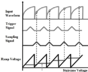
Sampling Method
Before each sampling cycle, a trigger pulse activates the oscillator, producing a linear ramp voltage. When the ramp voltage equals the staircase voltage, a sampling pulse is generated. The signal resolution depends on the step size of the staircase generator. Smaller steps result in better resolution and more accurate waveform reconstruction.
Types of Sampling Methods
Real-Time Sampling Method
In this method, a high-speed digitizer captures all sample points in a single sweep. It is mainly used to analyse transient, non-repetitive signals. Since each transient event is unique, adjacent samples cannot be related. This method requires very high sampling rates and high-speed memory.
Equivalent Sampling Method
This method works on repetitive signals. Samples are taken from successive cycles of the waveform and combined to form a complete signal. The reconstructed signal frequency can be much higher than the oscilloscope’s sampling rate. Equivalent sampling can be implemented using two techniques: random sampling and sequential sampling.
Random Sampling Method
This is the most commonly used equivalent sampling technique. It uses an internal clock that operates independently of the input signal. Samples are collected randomly and time-stamped, then reconstructed to form the waveform.
Sequential Sampling Method
In this method, samples are taken after a fixed incremental delay following each trigger event. With each successive trigger, the delay increases slightly until the entire waveform is reconstructed. This delayed sweep technique improves timing resolution and is commonly used to measure rise time and pulse modulation.
Advantages of Sampling Oscilloscope
- Capable of measuring extremely high-frequency signals
- Allows use of low-bandwidth amplifiers
- Efficient conversion of high-frequency signals to lower frequencies
- Fast data storage and response capability
Disadvantages of Sampling Oscilloscope
- Can only measure repetitive or continuous signals
- Frequency range depends heavily on circuit design
Applications of Sampling Oscilloscope
- Observation of high-speed electrical signals
- Accurate signal measurement and analysis
- Signal recording using external recorders
- Measurement of both high-frequency (hundreds of MHz) and low-frequency signals
- Analysis of signal parameters such as rise time and modulation
Sampling oscilloscopes are widely used in high-speed communication systems, research laboratories, and advanced electronic testing environments.