
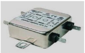
What is an EMI Filter?
An EMI Filter (Electromagnetic Interference Filter) is an electrical device or circuit used to reduce high-frequency electromagnetic noise generated by electronic and electrical equipment such as motors, power supplies, inverters, microprocessors, and clock circuits.
This electromagnetic noise typically ranges from 9 kHz to 10 GHz and can interfere with signal transmission as well as the proper functioning of electronic devices.
Importance of EMI Filters
Electromagnetic Compatibility (EMC) is a key factor in determining the quality and reliability of electronic systems. EMI filters help improve EMC by reducing interference, enhancing system performance, and extending the life of electronic equipment.
How Does an EMI Filter Work?
An EMI filter works by suppressing unwanted high-frequency noise while allowing the desired low-frequency signals or DC power to pass through. It mainly consists of passive components such as inductors and capacitors arranged in LC circuits:
- Inductors: Allow low-frequency signals to pass while blocking high-frequency noise
- Capacitors: Provide a low-impedance path to divert noise to ground
Electromagnetic interference is mainly caused by switching currents and power supply circuits. The EMI filter reduces this noise and ensures stable operation of devices.
Types of EMI Filters
1. Active EMI Filters
Active EMI filters use active components such as operational amplifiers along with passive elements to detect and cancel noise signals.
- Detect noise using current transformers
- Amplify noise signals
- Inject compensation signals to cancel interference
These filters are effective in low-level circuits but may have limited bandwidth compared to passive filters.
2. Passive EMI Filters
Passive EMI filters are made using inductors and capacitors arranged in LC networks to filter unwanted noise.
- Low cost and simple design
- No external power required
- Widely used in power supply systems
However, they are generally larger in size and may require multiple stages for effective filtering.
Electronic Ballast Using EMI Filter
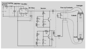
Ballast Circuit Diagram using EMI Filter
An electronic ballast circuit typically includes the following stages:
- EMI Filter
- Rectifier
- DC Filter
- Inverter
- Control Circuit
Circuit Working
The EMI filter stage reduces noise using an inductor (series) and capacitor (parallel). The rectifier converts AC to DC, while the DC filter smooths the output. The inverter converts DC into high-frequency AC, which is then stepped up using a transformer.
The control circuit regulates the entire system using feedback. The generated frequency typically ranges from 20 kHz to 80 kHz, and the transformer can increase voltage up to around 1000V for lamp ignition.
Advantages of EMI Filters
- Reduces electromagnetic interference
- Prevents equipment malfunction
- Improves system reliability
- Enhances electromagnetic compatibility (EMC)
- Protects devices from external noise
- Complies with EMC standards (EN 61000, EU Directive 2014/30/EU)
Disadvantages of EMI Filters
- May redirect unwanted noise back to the source
- Does not block radiated EMI without shielding
- Unshielded filters may emit noise into surroundings
- Can increase system size and cost
Applications of EMI Filters
- Industrial machinery and automation systems
- Medical equipment (MRI, diagnostic devices)
- Computer systems and power supplies
- Automotive battery chargers
- Aerospace and defense systems
- Fitness and consumer electronics
- Shielded rooms and testing chambers
Conclusion
EMI filters play a vital role in modern electronic systems by reducing electromagnetic interference and ensuring reliable performance. They are widely used across industries to improve signal integrity, comply with regulatory standards, and protect sensitive equipment. With the increasing use of electronic devices, EMI filters have become an essential component in maintaining system stability and performance.