

What is a Real-Time Clock (RTC)?
A Real-Time Clock (RTC) is an electronic clock module that keeps track of the current time and date. RTC devices are available as integrated circuits (ICs) and are widely used in embedded systems, computers, digital clocks, and automation projects. The DS1307 is one of the most popular RTC ICs. It is an 8-pin, low-power clock/calendar IC that communicates through the I2C (Inter-Integrated Circuit) interface and includes 56 bytes of battery-backed SRAM.
The DS1307 provides accurate information for seconds, minutes, hours, day, date, month, and year. It automatically adjusts the date at the end of each month, including leap-year compensation. One of the major advantages of the DS1307 is its battery backup feature, which allows the clock and calendar to continue operating even during power failures. The RTC consumes extremely low power while running on battery backup.
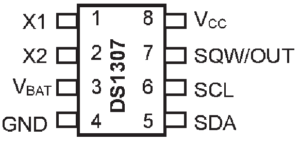
Pin Description of DS1307
Pin 1 (X1) and Pin 2 (X2)
These pins are connected to a 32.768 kHz quartz crystal oscillator. The internal oscillator circuit is designed to work with crystals having a 12.5 pF load capacitance. An external 32.768 kHz oscillator can also be connected to the X1 pin. In this case, the X2 pin remains unused.
Pin 3 (VBAT)
This pin is used for connecting a backup battery, typically a 3V lithium cell.
- Recommended battery voltage: 2V to 3.5V
- Provides backup power during main power failure
- Can maintain RTC operation for over 10 years with a suitable lithium battery
Pin 4 (GND)
Ground connection of the DS1307.
Pin 5 (SDA)
Serial Data Input/Output pin used for I2C communication.
- Open-drain bidirectional pin
- Requires an external pull-up resistor
- Supports pull-up voltages up to 5.5V
Pin 6 (SCL)
Serial Clock Input pin used for synchronization during I2C communication.
Pin 7 (SQW/OUT)
Square Wave Output pin. When enabled, this pin can generate one of the following frequencies:
- 1 Hz
- 4 kHz
- 8 kHz
- 32 kHz
This pin is also open-drain and requires an external pull-up resistor.
Pin 8 (VCC)
Primary power supply input. The device operates normally when VCC is within the specified operating range. When VCC falls below the threshold voltage, the DS1307 automatically switches to battery backup mode while maintaining timekeeping functions.
Features of DS1307 RTC
- Real-Time Clock (RTC) with calendar function.
- Tracks seconds, minutes, hours, date, day, month, and year.
- Automatic leap-year compensation up to the year 2100.
- 56 bytes of non-volatile RAM for data storage.
- Battery backup support.
- Automatic power-fail detection and switching.
- Consumes less than 500 nA in battery backup mode.
- Programmable square-wave output.
- Two-wire I2C communication interface.
- Available in 8-pin DIP and SOIC packages.
- Low power consumption.
- UL recognized component.
Working of DS1307 RTC
The DS1307 operates using a 32.768 kHz crystal oscillator connected between the X1 and X2 pins. This crystal provides the timing reference required for accurate clock and calendar functions. A 3V backup battery is connected to the VBAT pin, while the main supply voltage is connected to the VCC pin.
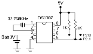
Under normal conditions, the RTC operates using the VCC supply. If the main power fails, the DS1307 automatically switches to the backup battery and continues keeping time. Communication between the DS1307 and a microcontroller takes place through the I2C bus using two lines:
- SDA – Serial Data Line
- SCL – Serial Clock Line
I2C Communication Process
The DS1307 follows the standard I2C communication protocol.
1. START Condition
Communication begins when the SDA line changes from HIGH to LOW while the SCL line remains HIGH.
2. Device Address and Register Selection
The master device sends the DS1307 device address followed by the desired register address.
3. Data Transfer
Data is transferred serially through the SDA line and synchronized by the SCL clock signal.
4. Acknowledgement
After every byte transfer, the receiving device sends an acknowledgement bit.
5. STOP Condition
Communication ends when the SDA line changes from LOW to HIGH while SCL remains HIGH.
Bus Conditions in DS1307
START Condition
A START condition occurs when the data line changes from HIGH to LOW while the clock line remains HIGH.
STOP Condition
A STOP condition occurs when the data line changes from LOW to HIGH while the clock line remains HIGH.
Data Validity
Data on the SDA line must remain stable during the HIGH period of the clock signal. Changes to the data line should occur only during the LOW period of the clock signal.
Advantages of DS1307 RTC
- Maintains accurate time and date information.
- Battery backup ensures operation during power failures.
- Low power consumption.
- Simple I2C interface requiring only two communication lines.
- Built-in calendar with leap-year correction.
- Provides additional non-volatile RAM storage.
- Easy interfacing with microcontrollers and embedded systems.
Applications of DS1307 RTC
- Digital clocks and calendars.
- Embedded systems.
- Microcontroller projects.
- Data logging systems.
- Computer motherboards.
- Industrial automation equipment.
- Smart energy meters.
- Home automation systems.
- Attendance monitoring systems.
- IoT-based timekeeping applications.
Conclusion
The DS1307 is a low-power Real-Time Clock IC that provides accurate time and calendar functions with battery backup support. Its simple I2C interface, built-in SRAM, low power consumption, and automatic power-fail switching make it a popular choice for embedded systems, digital clocks, data loggers, and industrial applications.