

By Ruiwen Dong, Electronics Engineer at SpeedUp
“Design a small connected device that receives and displays messages.” It sounds like a clear request, but it is still a product idea rather than a circuit-design input. What receives the message? How often? From which power source? What does “small” mean, and how quickly must the display update? A schematic produced from this sentence may look plausible while quietly embedding assumptions that the product team never approved.


A useful hardware product brief does not need to become a long formal specification. It does, however, need to separate confirmed requirements from preferences and open decisions. Five categories are usually enough to give an engineer – or an AI circuit-design system – a much firmer starting point.


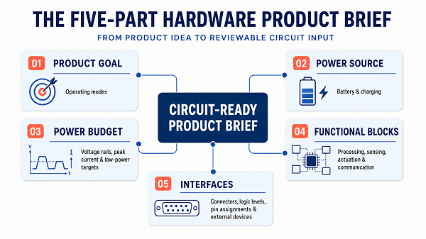
1. Product Goal and Operating Modes
Begin with one testable sentence that connects input, processing and output. For example: “The device shall receive a text payload over Wi-Fi, extract the latest approved message and show it on an e-ink display.” This is more useful than “build a smart message card” because it establishes a functional path that can be divided into blocks.
Next, describe the operating states. A battery-powered connected display might be off, asleep, connecting to Wi-Fi, subscribed to an MQTT topic, updating the display or reporting an error. The brief should also identify the events that cause transitions: a timer expires, a new message arrives, a button is pressed or a charger is connected.
Subjective words should become observable behaviour. Replace “fast” with “show a new message within 10 seconds of receipt”. Replace “low power” with a runtime target and an update pattern. If the target is not yet known, mark it as TBD rather than allowing the circuit designer to guess.
2. Power Source, Battery and Charging
Power decisions influence the regulator, connector, protection, board area and thermal design, so they cannot be postponed without consequences. List every intended source: primary battery, rechargeable battery, USB, external adaptor or a combination.
For battery operation, state whether the cell is primary or rechargeable, the chemistry, the cell count and the expected voltage range. “Battery powered” could mean two alkaline cells that gradually fall below 2 V, a single lithium-ion cell that reaches 4.2 V when fully charged, or a regulated battery pack. Each choice leads to a different power tree.
Charging requirements need the same clarity. State the charging input, the desired connector and whether the product must operate while charging. If a single-cell rechargeable battery is only preferred, write “Preferred: one-cell lithium-ion; exact capacity TBD.” If operation during charging is undecided, keep it visible as a design decision because it can change the charger and power-path architecture.
3. Power Rails, Peak Current and Low-Power Targets
A brief should list the rails required by the processor, wireless subsystem, display, sensors and external devices. It should also distinguish average current from short-duration demand. A low average does not guarantee that a regulator, battery or decoupling network can support a radio transmission or display refresh without a voltage dip.
For an ESP32-C3 design, for example, Espressif’s hardware-design guidance recommends a 3.3 V supply capable of at least 500 mA and highlights the sudden increase in current during transmission. That is a sizing input, not a prediction that the finished product will continuously draw 500 mA.
Runtime should be expressed through operating states and duty cycle. A simple first estimate is:
Average current = sum of (state current x fraction of time in that state)
The brief does not need final measured currents, but it should state the expected pattern: wake every minute, connect only when required, refresh the display after a changed message, then return to sleep. It should also record a target such as “30 days between charges under the stated update profile”. Measurements can replace estimates after the prototype exists.
4. Microcontroller, Sensing, Actuation and Communication
Describe the microcontroller or processor by capability before locking a part number. Relevant requirements may include memory, security features, hardware timers, ADC channels, USB, SPI, I2C, UART, PWM or a wireless radio. Mark a component as mandated, preferred or open so the designer knows whether alternatives are allowed.
Apply the same discipline to every functional block. A sensor requirement should include range, accuracy, sample rate and electrical interface. An actuator requirement should include voltage, current and control method. These details determine far more than the name of the component.
Communication also has layers. Wi-Fi defines the wireless link, while MQTT defines application messaging. Writing “uses MQTT” does not specify the radio, antenna, provisioning method, broker security, reconnect behaviour or whether messages must be stored when the network is unavailable. Hardware and firmware responsibilities become much clearer when the link technology and application protocol are recorded separately.
5. Connectors, Logic Levels, Pin Assignments and External Devices
External and inter-board connections deserve their own interface list. For each signal, record its direction, logic voltage, power ownership and mandatory control behaviour. Pull-ups, interrupts, enables, resets and chip-select lines should be included whenever they affect the circuit.
An e-ink interface might begin like this:
| Signal | Direction at MCU | Level | Requirement |
| 3V3 | Power out | 3.3 V | Display supply; current during refresh TBD |
| SCK, MOSI | Output | 3.3 V logic | SPI clock and display data |
| CS, DC | Output | 3.3 V logic | Chip select and data/command control |
| RST_N | Output | 3.3 V logic | Active-low display reset |
| BUSY | Input | 3.3 V logic | Display status; active level confirmed from panel datasheet |
This table is intentionally compact, but it exposes several decisions that a one-line product idea hides. The exact display must still be selected, its connector pinout verified and its voltage tolerance checked. Fixed MCU pins should be labelled “confirmed”; flexible pins can remain “preferred” until boot-strapping, debug and layout constraints have been reviewed.
Worked Example: From Product Idea to Circuit-Ready Brief
Consider the starting request: “Design a small card that receives and displays messages, using an e-ink screen, based on an ESP32 + Wi-Fi + MQTT solution.”
The worked example is based on a SpeedUp-generated review bundle containing a product prompt, a system block diagram and exported schematic views. It is useful architecture evidence, not a tested or production-ready design. A more circuit-ready brief could add the following:

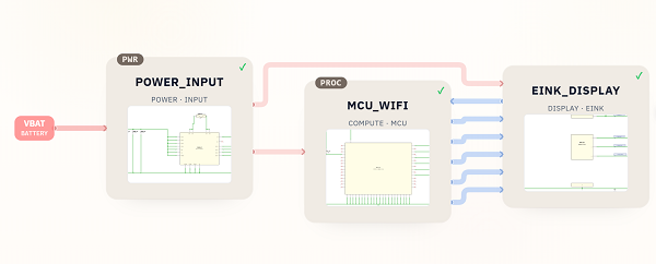
- Product behaviour – Confirmed: receive text through Wi-Fi/MQTT and display the latest valid message on e-ink. Preferred: refresh only when content changes. TBD: maximum message length and acceptable delivery-to-display delay.
- Power source – Preferred: rechargeable single-cell battery with USB charging. TBD: cell capacity, connector type and operation while charging.
- Power budget – Confirmed:3 V logic. Preferred: regulator sized for the ESP32 transmission requirement plus display-refresh demand. TBD: sleep current and runtime target.
- Functional blocks – Confirmed: ESP32-C3 Wi-Fi controller, battery-to-3.3 V power path and e-ink display interface. TBD: exact panel, regulator and protection devices.
- Interfaces – Confirmed: SPI-style SCK, MOSI, CS and DC, plus reset and busy signals. TBD: final pins, FPC connector and active levels.

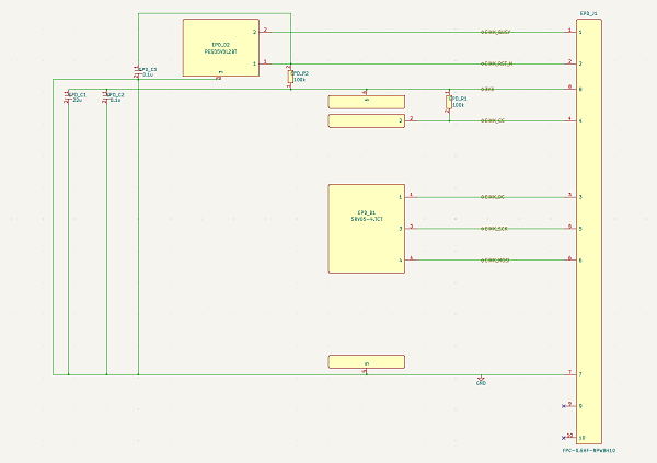
From this brief, a designer can draw a block diagram, draft a preliminary power tree, shortlist parts and create a first schematic without pretending that every product decision is settled. More importantly, reviewers can see which choices came from the product team and which remain assumptions.
The Reusable Five-Part Brief
For a new project, start with five fields:
- Product behaviour: What is the input, processing action and output? What operating states and transitions are required?
- Power source: Which sources are supported? What battery, charging and power-path decisions are fixed?
- Power budget: Which rails are needed? What are the peak-load, sleep-current and runtime targets?
- Functional blocks: What processing, sensing, actuation and communication capabilities are required?
- Interfaces: Which connectors, signals, directions, logic levels and fixed pins must be supported?
Label every entry Confirmed, Preferred or TBD. Before handing the brief to an engineer or design system, check that measurable targets have replaced vague adjectives, peaks are separated from averages, protocols are separated from physical links and every external connection has an owner.
Where AI Circuit Design Fits
Explicit requirements can be mapped into functional blocks, a power architecture, candidate components and a first schematic. AI can accelerate that translation and expose missing decisions, but it cannot approve the assumptions that the brief leaves unstated.
The resulting schematic remains an engineering draft. Component limits, battery behaviour, RF performance, protection, PCB layout, firmware, sourcing, safety, compliance and manufacturing all require downstream review and validation.
Conclusion: Better Inputs Reduce Wrong-Direction Iteration
Product behaviour, power source, power budget, functional blocks and interfaces form a compact bridge between an idea and a reviewable circuit. Defining them early does not remove iteration. It makes the first iteration useful, because the schematic begins with visible requirements instead of invisible guesses.
Author bio: Ruiwen Dong is an Electronics Engineer at SpeedUp, focused on electronic system architecture and AI-assisted workflows for circuit design.