
Introduction
Anderson’s Bridge is an AC bridge circuit used for measuring the self-inductance of a coil with high accuracy. Developed by Alexander Anderson in 1891, it is a modified form of Maxwell’s Inductance–Capacitance Bridge. Unlike Maxwell’s bridge, Anderson’s Bridge uses a fixed standard capacitor instead of a variable one, allowing more precise measurement, especially for low-Q coils (Q < 1).
Construction of Anderson’s Bridge
The bridge has four arms: AB, AD, BC, and CD.
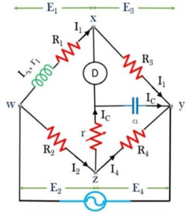
- Arm AB: Contains the unknown inductance L1 in series with a non-inductive resistance R1 (plus internal coil resistance r1).
- Arms AD, BC, and CD: Contain known non-inductive resistances R2, R3, and R4.
- Junction E: Connected to a variable resistor r between E and D, a standard capacitor C between E and C, and the null detector between E and B.
The standard capacitor is placed in series with the adjustable resistance r, and this combination is connected in parallel with arm CD. A power source is applied between points B and E.
Theory of Anderson’s Bridge
At balance, the relationships between the voltages and currents in the arms must satisfy the AC bridge condition. Using Kirchhoff’s laws, the balance equations are obtained by equating voltage drops in the appropriate loops.
After substituting the current through the capacitor and separating real and imaginary components, the equations for the unknown inductance L1 and resistance r1 are derived.
The balance equation for the inductance is more complex compared to Maxwell’s Bridge, which is why alternate adjustment of r and R1 is recommended to achieve faster convergence.
How to Measure Unknown Inductance Using Anderson’s Bridge
- Apply a signal generator voltage at an audible frequency.
- Select the desired inductor value on the measurement device.
- Turn on the power and note the millivoltmeter deflection.
- Adjust resistance and capacitance values until the null detector shows zero (null point).
- Record the values of R1 and r using a multimeter.
- Use the derived balance formula to compute the unknown inductance.
- Repeat the experiment with different standard capacitor values for accuracy.
Working of Anderson’s Bridge
The bridge measures self-inductance by comparing the unknown inductance with a known standard capacitor. It operates similarly to Maxwell’s Bridge but eliminates the need for a variable capacitor.
The circuit includes:
- A standard capacitor
- A resistor in series with the capacitor
- An oscillator tuned near the resonant frequency of the coil
By measuring the impedance of this resonant network with a digital multimeter, the value of self-inductance is calculated. Since the capacitor used is fixed, measurement is more stable and less error-prone.
Advantages
- Uses a fixed capacitor, unlike Maxwell’s bridge which requires a variable capacitor.
- Provides highly accurate measurement of inductance, even in the millihenry range.
- Suitable for low-Q coils where other bridges fail to converge easily.
- Can also compute capacitance in terms of inductance.
Disadvantages
- More complex circuit with additional components compared to other AC bridges.
- Balance equations are lengthy and difficult to simplify.
- Additional junction point makes it harder to shield from stray capacitance.
Applications
- Measurement of self-inductance (L) of coils
- Determination of inductive reactance (XL) at a given frequency
- Used in AC bridge laboratories and calibration systems
- Testing low-Q inductors


