Introduction
A 555 timer IC is a great electronic component that is able to generate oscillating waveforms as outputs with configurable delays, which helps with the switching of various electronic circuits. This timer IC is very easy to use and easy to source, so in this article, we will discuss the 3 most common types of multivibrator circuit modes using the 555 timer IC
- Astable Mode
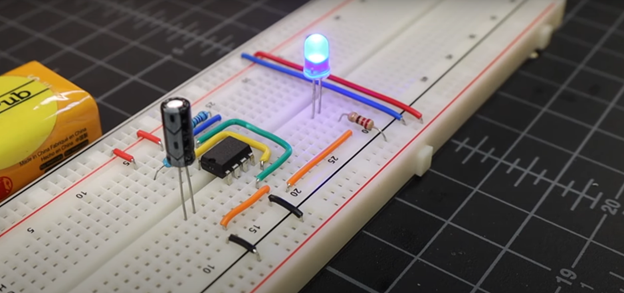
The Astable mode of the Multivibrator circuit continuously switches between the high and the low state; it has no stable state. The oscillating output makes it a great choice for generating clock pulses, especially square wave signals needed in the digital world.
Circuit configuration:
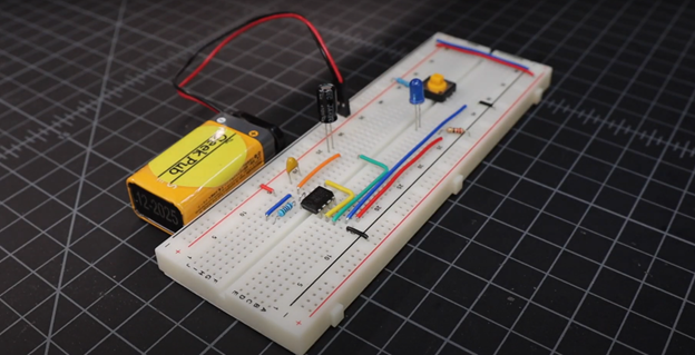
The Astable mode consists of two resistors, R1 connected between supply and the discharge pin and an R2 resistor connected in series with R1 between the discharge and the trigger pin. The capacitor C1 is connected to the threshold and trigger pin while its other end is grounded.
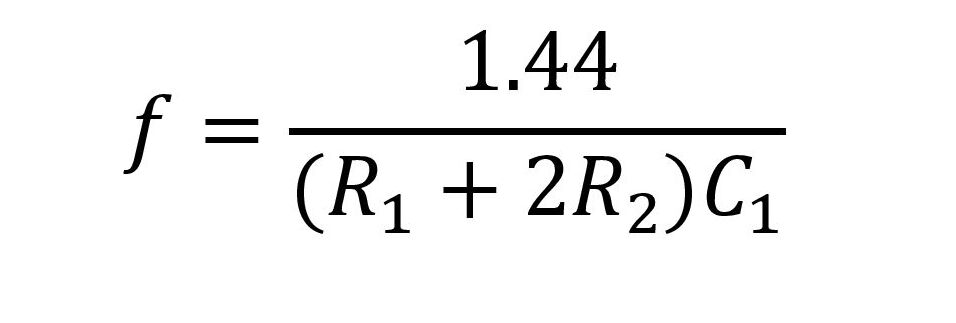
The capacitor is responsible for the duty cycle of the circuit as it charges and discharges, generating the pulsating output. To control the output frequency, the circuit needs to control the charging and discharging of the capacitor, and to do that, you will need to vary the resistance of the R1 resistor.
To calculate the output frequency, you can use the following formula:
Applications:
- LED flashing circuits, as the capacitor at the output helps generate pulsating waveforms.
- Tone Generators, with the help of frequency modulation.
- Digital clock circuits, to generate clock signals for enabling various flip-flops and other latching circuits.
- Monostable Mode
The Monostable mode of operation has a single state, as the name suggests. This circuit works when the user triggers the 555 timer IC by pressing a momentary switch. The output is kept high for a brief period of time before returning to its stable low state.
Circuit configuration:
The Monostable circuit features a much simpler circuit as it only needs one resistor, a capacitor, and a momentary switch to trigger the 555 timer IC. The Resistor R is connected between the supply and the threshold pin, while the capacitor C is connected at the discharge pin of the timer IC. The switch is connected to the trigger pin to help trigger the IC whenever the switch is pressed.
To adjust the time duration for which the output stays high, you can adjust the value of Resistor R and capacitor C using the formula given below:

Increasing the value of the resistor or the capacitor can help increase the duration of the output state by keeping it high for a longer period of time.
Applications:
- Used in a timer delay circuit, especially in appliances such as washing machines and microwave ovens
- Used in digital signals to extend short pulses
- Used in Camera flash triggering by delaying the flash circuit once the picture is taken
- Bistable Mode
The Bistable mode, as the name suggests, features 2 stable output states. It can remain high as long as necessary, unless it is triggered to change its state to low.
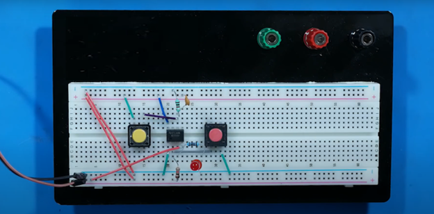
This circuit features two momentary switches, one of which is used to trigger the high state output while the other is for the low state output both are considered stable. The Bistable configuration does not rely on a timing capacitor and it also does not require resistors for controlling the charging and discharging speeds of the capacitor.
Circuit configuration:
Initially the output of this circuit is set to low. When the switch 1 connected between trigger and ground is pressed, the output is High even if the switch button is released. This is the first stable output state, HIGH.
When switch 2 connected between Vcc and Threshold pin is pressed, the output is switched to LOW, triggering the second stable state of the circuit.
Applications:
- Used as Flip Flops and Latching circuits as it can store the state of the output.
- Can be used as a simple push button circuit in appliances.
- Can be used to store 1 bit digital logic.
Conclusion
The 555 timer IC is a great piece of electronic component as it can teach you a lot about the world of digital electronics. This simple circuit can be a beginner friendly project for anyone looking to get into the world of electronics and digital circuits.
To learn more about 555 timer circuits, check out our article on Speed Controller using the 555 timer circuit to take your electronics knowledge to the next level.
To source electronic components and your very own 555 timer IC check out Flywing Tech.