• Home
  • About Us
  • Contact Us
Semiconductor for You
  • Home
  • Semiconductor News
  • Technology
    • Automotive
    • Consumer Electronics
    • IoT
    • Lighting
    • Power Management
    • Wireless
    • Personal Electronics
    • Hardware & Software
    • Research
    • Medical Electronics
    • Embedded Design
    • Aerospace & Defence
    • Artificial Intelligence
  • DIY Projects
  • Market
  • Industries
    • Renesas Electronics
  • Knowledge Base
  • Events
  • Tools
    • Resistor Color Code Calculator
No Result
View All Result
Semiconductor for You
No Result
View All Result
Home Knowledge Base

Basic of Tuned Radio Frequency Receiver : TRF and Limitations

Nikita Bisen by Nikita Bisen
September 13, 2022
in Knowledge Base
0
ADVERTISEMENT

The TRF, tuned radio frequency radio receiver was widely used in the early days of radio, but is hardly used today

  • This receiver was popular in the 1920s and a TRF is a type of radio receiver that is controlled by one or more RF amplifier stages followed by a detector circuit to extract the audio signal and usually an audio frequency amplifier.
  • Early models could be uninteresting to operate because when tuning in a station each stage had to be individually adjusted to the station’s frequency.
  • But now latest models had ganged tuning, the tuning mechanisms of all stages being linked together, and operated by just one control knob.
  • In the 1930’s it was replaced by the superheterodyne receiver patented by Edwin Armstrong.
Block Diagram of TRF Receiver
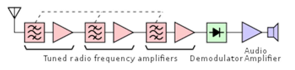
  • It consisted of three section RF amplifier, demodulator, and audio amplifier.
  • The signal received from the antenna is weak and noisy so this signal is given to a broadband RF amplifier.
  • This RF amplifier enhances the signal-to-noise ratio and amplifies the signal. Then this signal passed through AM detector or demodulator.
  • The output of AM detector or demodulator is an audio signal. The detected audio signal is then amplified by the audio power amplifier.
  • The audio amplifier output give to the speaker and then it finally produces the sound.
  • The RF amplifier is tuned to a specific frequency that is to be received. Hence if another frequency is to receive, then another TRF receiver should be used.
  • By using the RF amplifier tuned to a wide range of frequencies this problem is solved. But this reduces the selectivity of the receiver.

Advantages of TRF Receiver

  • Simplest type of receiver since it does not involve mixing and IF operation.
  • Very much suitable to receive single frequency.
  • TRF receivers have good sensitivity.

Disadvantages of TRF Receiver

  • Bandwidth changes with center frequency, when the TRF receiver is used to receive a wide range of frequencies.
  • Multiple stages of RF amplifiers are used. This can lead to instability since they all are tuned to the same center frequency. Hence stagger tuning is to be used.
  • The gain of the TRF receiver is not uniform over a wide range of frequencies.

Application of TRF Receiver

  • It was used in the early days of wire-less technology but it is rarely used today as other techniques offering much better performance are available.

Limitations of TRF Receiver

  • It suffers from variations in BW over the tuning range ( s 40 – 1650 kHz).
  • The gain of TRF RX is not uniform over the tuning range.
  • The TRF is unstable at high frequency.
  • Gang tuning of more capacitors simultaneously is difficult.
Content Protection by DMCA.com
Nikita Bisen

Nikita Bisen

Browse by Category

  • Aerospace and Defence
  • Articles
  • Automotive
  • Consumer-Electronics
  • Hardware & Software
  • Interview
  • IoT
  • Knowledge Base
  • Lighting
  • Market
  • personal-electronics
  • Power Management
  • Research
  • Semiconductor Events
  • Semiconductor News
  • Technology
  • Wireless
Semiconductor for You

Semiconductor For You is a resource hub for electronics engineers and industrialist. With its blend of
technology features, news and new product information, Semiconductor For You keeps designers and
managers up to date with the fastest moving industry in the world.

Follow Us

Browse by Category

  • Aerospace and Defence
  • Articles
  • Automotive
  • Consumer-Electronics
  • Hardware & Software
  • Interview
  • IoT
  • Knowledge Base
  • Lighting
  • Market
  • personal-electronics
  • Power Management
  • Research
  • Semiconductor Events
  • Semiconductor News
  • Technology
  • Wireless

Recent News

TDK introduces automotive power-over-coax inductor for filters with industry-leading simplicity and efficiency

TDK introduces automotive power-over-coax inductor for filters with industry-leading simplicity and efficiency

June 17, 2025
Mouser Electronics Gears Up for the 6th Edition of India IoT Technical Roadshow

Mouser Electronics Gears Up for the 6th Edition of India IoT Technical Roadshow

June 17, 2025
  • About
  • Advertise
  • Privacy & Policy
  • Contact

© 2022 Semiconductor For You

No Result
View All Result
  • Home
  • Semiconductor News
  • Technology
    • IoT
    • Wireless
    • Power Management
    • Automotive
    • Hardware & Software
  • Market
  • Knowledge Base
  • Tools
    • Resistor Color Code Calculator

© 2022 Semiconductor For You