• Home
  • About Us
  • Contact Us
Semiconductor for You
  • Home
  • Semiconductor News
  • Technology
    • Automotive
    • Consumer Electronics
    • IoT
    • Lighting
    • Power Management
    • Wireless
    • Personal Electronics
    • Hardware & Software
    • Research
    • Medical Electronics
    • Embedded Design
    • Aerospace & Defence
    • Artificial Intelligence
  • DIY Projects
  • Market
  • Industries
    • Renesas Electronics
  • Knowledge Base
  • Events
  • Tools
    • Resistor Color Code Calculator
No Result
View All Result
Semiconductor for You
No Result
View All Result
Home Knowledge Base

Basics of Voltage Standing Wave Ratio

Mrinali Sharma by Mrinali Sharma
October 20, 2022
in Knowledge Base
0
ADVERTISEMENT
  • Voltage standing wave ratio (VSWR) is defined as the ratio between transmitted and reflected voltage standing waves in a radio frequency (RF) electrical transmission system.
  • It is a measure of how efficiently RF power is transmitted from the power source, through a transmission line, and into the load.
Diagram of Voltage Standing Wave Ratio
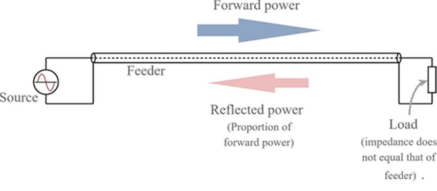
  • A common example is a power amplifier connected to an antenna through a transmission line.
  • SWR is the ratio between transmitted and reflected waves.
  • A high SWR indicates poor transmission-line efficiency and reflected energy, which can damage the transmitter and decrease transmitter efficiency.
  • Since SWR commonly refers to the voltage ratio, it is usually known as the voltage standing wave ratio (VSWR).

The Standing Wave

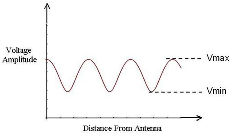
  • A standing wave, also called a stationary wave, combination of two waves moving in opposite directions, each having the same amplitude and frequency.
  • The phenomenon is the result of interference; that is, when waves are superimposed, their energies are either added together or canceled out.

Mathematically

  • VSWR is the voltage ratio of the signal on the transmission line:
    VSWR = |V(max)| / |V(min)|
  • where V(max) is the maximum voltage of the signal along the line, and V(min) is the minimum voltage along the line.

It can also be derived from the impedances:

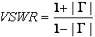
  • VSWR = (1+gamma)/(1-gamma)
    where gamma (gamma) is the voltage reflection coefficient near the load, derived from the load impedance (ZL) and the source impedance (Zo):
    gamma = (ZL-Zo)/(ZL+Zo)
    If the load and transmission line is matched, gamma = 0, and VSWR = 1.0
Content Protection by DMCA.com
Mrinali Sharma

Mrinali Sharma

Browse by Category

  • Aerospace and Defence
  • Articles
  • Automotive
  • Consumer-Electronics
  • Hardware & Software
  • Interview
  • IoT
  • Knowledge Base
  • Lighting
  • Market
  • personal-electronics
  • Power Management
  • Research
  • Semiconductor Events
  • Semiconductor News
  • Technology
  • Wireless
Semiconductor for You

Semiconductor For You is a resource hub for electronics engineers and industrialist. With its blend of
technology features, news and new product information, Semiconductor For You keeps designers and
managers up to date with the fastest moving industry in the world.

Follow Us

Browse by Category

  • Aerospace and Defence
  • Articles
  • Automotive
  • Consumer-Electronics
  • Hardware & Software
  • Interview
  • IoT
  • Knowledge Base
  • Lighting
  • Market
  • personal-electronics
  • Power Management
  • Research
  • Semiconductor Events
  • Semiconductor News
  • Technology
  • Wireless

Recent News

New SPI Absolute Encoder Supports 9 mm to 15.875 mm Motor Shafts

New SPI Absolute Encoder Supports 9 mm to 15.875 mm Motor Shafts

June 11, 2025
Infineon Secures the Future with 10 Billion Integrity Guard Chips Delivered

Infineon Secures the Future with 10 Billion Integrity Guard Chips Delivered

June 11, 2025
  • About
  • Advertise
  • Privacy & Policy
  • Contact

© 2022 Semiconductor For You

No Result
View All Result
  • Home
  • Semiconductor News
  • Technology
    • IoT
    • Wireless
    • Power Management
    • Automotive
    • Hardware & Software
  • Market
  • Knowledge Base
  • Tools
    • Resistor Color Code Calculator

© 2022 Semiconductor For You