Introduction
A beat frequency oscillator (BFO) is a dedicated oscillator in a radio receiver that generates an audio-frequency
signal from Morse code (CW) transmissions, making them audible. The BFO mixes its signal with the incoming radio signal to produce a beat frequency, which can be heard as a tone. BFOs are also used to demodulate single-sideband (SSB) signals by restoring the suppressed carrier.
 BFOs are commonly found in communication receivers used by amateur radio operators and shortwave listeners. Reginald Fessenden, a Canadian engineer, invented the BFO in 1901, marking the first use of the heterodyne principle. A BFO generates an audio-frequency output that varies over a wide range. This wide range can be covered with a single dial rotation, making it suitable for precise tuning.
Working of Beat Frequency Oscillator
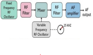
A BFO consists of two separate RF oscillators: one operating at a fixed frequency and the other at a variable frequency. These two signals are fed into a mixer, which produces the sum and difference of their frequencies. The difference frequency is designed to fall within the audio frequency range.
An RF filter removes all high-frequency components, allowing only the AF difference signal to pass. This AF output is then amplified for further processing.
Why BFO Output is Useful
- Small changes in oscillator frequency cause large changes in the difference frequency.
- BFOs provide a continuous range of audio frequencies from a few Hz to the complete AF range.
- Amplitude remains nearly constant throughout the tuning range.
Importance of Stability
The stability of oscillators is crucial because small drifts in their frequency affect the difference frequency significantly.
To ensure accuracy:
- Each oscillator must have high temperature and voltage stability.
- The two oscillators must be completely isolated to prevent synchronization.
If coupling occurs, the oscillators may lock together, making small difference frequencies impossible and introducing distortion.
Spurious Signals (Whistles)
Spurious beat notes, also known as whistles, are produced due to cross-modulation in the AF amplifier. These errors occur when high-order RF harmonics enter the amplifier.
They can be reduced by:
- Minimizing harmonic generation in the mixer
- Using proper filtering
- Shielding sensitive circuit sections
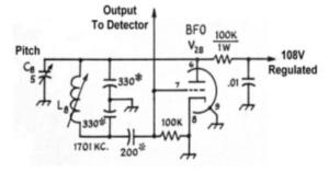
Circuit Diagram Explanation
A typical BFO operates between 1698 kHz and 1702 kHz. The BFO/Pitch control adjusts the frequency depending on whether the receiver is handling CW, USB, or LSB signals.
Key Components
1. Oscillator Tank Circuit
The tank circuit includes coil L8 and two 330 pF capacitors in series. Together they form a 165 pF effective capacitance. This combination resonates with L8 to determine the oscillator frequency.
2. BFO/Pitch Control
A small variable capacitor (C8) is used to adjust the oscillator frequency. This allows precise tuning for USB, LSB, or CW reception.
3. Grid Capacitor
It couples the tank circuit to the tube grid while blocking plate voltage.
4. Grid Leak Resistor
Provides grid leak bias by rectifying the grid current.
5. 6CG7 Vacuum Tube
A dual triode tube, with one triode acting as the oscillator and the other as the detector.
6. Load Resistor
A 100k resistor serves as the oscillator load. Voltage across it varies with plate current.
7. Plate Decoupling Capacitor
A 0.01 μF capacitor grounds any stray RF passing through the load resistor, preventing it from entering the B+ supply.
8. Regulated Plate Voltage
The BFO is powered by a regulated 108V supply to ensure frequency stability.
9. Output to Detector
The BFO output is taken from the grid (not the plate) to avoid excessive signal strength. This output is coupled to the detector for mixing.
Most Influential Factors on BFO Performance
- High frequency stability of oscillators
- Minimal frequency drift due to temperature or voltage changes
- No coupling between oscillators
Limitations
- More complex circuitry because it requires two oscillators
- Requires precise stability and isolation
Applications of Beat Frequency Oscillator
- Used to cover a wide audio frequency range with a single tuning dial
- Historically used in communication receivers for CW and SSB
- Used in metal detection devices due to its high accuracy
- Now replaced by modern oscillators such as the Wien bridge oscillator