- Combinational circuits are a type of digital logic circuit in which the instantaneous output is solely determined by the combination of its inputs. A combinational circuit, for example, could be used to add or subtract any number of inputs, or to perform other mathematical operations. In fact, one of the primary applications of combinational circuits is to perform “Boolean Algebra,” which refers to the execution of basic mathematical operations with binary numbers.
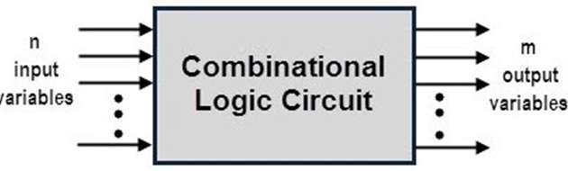
- In the above figure, there are n input variables and hence there will be 2n possible combinations of bits at the input. Each output is expressed using a Boolean expression of input variables. As a result, the output of the above generalized combinational logic circuit can be expressed using m Boolean expressions.
- A combinational circuit usually has multiple inputs and one or more outputs. Because it is a digital circuit, the input values must be either 0 or 1. The outputs must also have a value of 0 or 1. An Adder circuit would take all of the inputs’ instantaneous values, add them together, and output the sum of the inputs. When the inputs are changed, the output changes almost instantly. Combinational logic circuits, unlike sequential logic circuits, do not have memory; their outputs are solely dependent on the current state of the inputs.
- These circuits are built with logic gates such as AND, OR, NOT, NAND, and NOR. These logic gates serve as the foundation for combinational circuits. Combinational logic circuits are similar to these circuits in that they do not rely on previous input to generate any output. The output of a combinational circuit is always a direct function of the applied external inputs.
Classification of Combinational Logic Circuits
- Combinational circuits are used in a wide range of applications such as calculators, digital measuring techniques, computers, digital processing, automatic machine control, industrial processing, digital communications, and so on.
- For various applications, various types of combinational logic circuits are used.
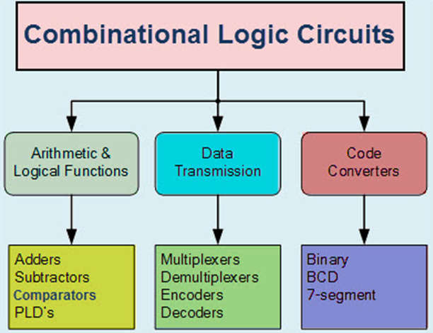
- Combinational logic circuits are classified into three types based on their function, namely Arithmetic and logic circuits, data transmission circuits, and code converter circuits.
Functions of Combinational Logic Circuit
- The three approaches to representing combinational logic circuits are discussed here.
- Logic gates – These are the fundamental building blocks in the design of combinational logic circuits. All logic gates are NAND, NR, NOT, NOR, OR, and AND.
- Boolean algebra – This representation specifies the relationship between Boolean variables and is used to design digital circuitry using logic gates. Because every digital system is built with logic gates, Boolean algebra is the most common way to represent a combinational logic circuit.
- Truth table – This method computes the operational values of logical expressions for every possible combination of logical variable values. A truth table is required to represent the logic for each single-bit output in the logic block. All of the output columns are typically represented in a single table.
Truth Table
- The logic gate function can be defined using its truth table, which contains outputs for all possible logic gate input combinations. The figure below depicts an example combinational logic function truth table.
| C | B | A | Q |
|---|---|---|---|
| 0 | 0 | 0 | 0 |
| 0 | 0 | 1 | 0 |
| 0 | 1 | 0 | 0 |
| 0 | 1 | 1 | 0 |
| 1 | 0 | 0 | 1 |
| 1 | 0 | 1 | 0 |
| 1 | 1 | 0 | 0 |
| 1 | 1 | 1 | 0 |
Boolean Algebra
- The output of a combinational logic function can be expressed using Boolean algebra, and an example of a Boolean expression for the above truth table is shown in the figure below.
![]()
Logic Diagram
- A logic diagram is a graphical representation of combinational logic functions using logic gates. The logic diagram for the previously discussed logic function truth table and Boolean expression is depicted in the figure below.
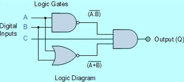
- Because they are built with individual logic gates, combinational logic circuits are also known as decision-making circuits. Combinational logic is the process of combining logic gates to process two or more inputs so that at least one output signal is generated based on the logic function of each logic gate.