A sinusoidal waveform without any DC offset can be completely defined by its frequency, phase difference, and amplitude relative to a reference signal. In most AC power systems, only one frequency is used. This means that all voltages and currents in the circuit share the same frequency, so we typically focus on amplitude and phase when analyzing AC circuits.
The Role of Complex Numbers in AC Analysis
Since amplitude and phase are the two main variables that vary within a circuit, we need an analysis method that allows us to handle both efficiently. Complex numbers provide exactly that. A complex number can be expressed as a vector that represents both magnitude and phase, making it ideal for AC circuit calculations.
In mathematical terms, a complex number has two parts — a real component and an imaginary component. This form enables engineers to work easily with quantities that vary sinusoidally over time.
Understanding Phasors
Phasors are complex numbers used to represent sinusoidal voltages or currents. The magnitude of the phasor corresponds to the peak (maximum) value of the sinusoidal waveform, and the phase angle corresponds to its phase difference relative to a cosine waveform.
The phase shift describes how much a signal is displaced in time compared to a zero-phase reference signal. Mathematically, a zero-phase signal is a cosine waveform. However, in real AC systems, there is no clear starting or stopping point, so one of the signals is chosen as a reference and treated as the cosine wave.
Typically, the system’s main input voltage is selected as the reference signal, and it is assumed to have a phase of zero degrees. All other voltages and currents in the system are then described with respect to this reference phase.
Phasors as Mathematical Tools
It is important to understand that phasors are simply a practical application of standard mathematical principles. They make it easier to represent and manipulate sinusoidal quantities in AC analysis. For example, a voltage waveform with an amplitude of 5 V and a phase shift of 36.87° can be expressed as a phasor:
5 ∠ 36.87°
This notation is known as the polar form of a phasor, where the magnitude represents the amplitude and the angle represents the phase difference.
Rectangular (Complex) Form of a Phasor
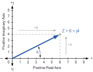
Another way to represent a phasor is in rectangular form, expressed as a complex number with real and imaginary components. In electrical engineering, the imaginary part of a complex number is denoted by the letter j (instead of i, which commonly represents current).
Thus, a phasor in rectangular form can be written as:
V = a + jb
Here, a represents the real component (in-phase part of the signal) and jb represents the imaginary component (the quadrature or 90° out-of-phase part). The relationship between the polar and rectangular forms is expressed as:
V = A ∠ θ = A(cosθ + j sinθ)
Conclusion
Complex numbers and phasors form the mathematical foundation of AC circuit theory. They provide a simple yet powerful way to represent sinusoidal quantities, making circuit analysis more efficient and intuitive. Understanding how to represent AC signals using phasors is essential for studying impedance, power, and phase relationships in electrical engineering.