
Introduction
A digital frequency meter is an electronic instrument used to measure the frequency of a sinusoidal signal with high precision—often up to three decimal places. It works by converting the input waveform into continuous unidirectional pulses and counting these pulses within a fixed time interval. Typically, digital frequency meters can measure frequencies ranging from 104 to 109 Hz.
Digital frequency meters are used to measure the frequencies of sound and light waves. Frequency is defined as the number of occurrences of a specific waveform within a given period. The meter detects and displays frequencies that may be above or below the range detectable by the human eye or ear.
The input signal of a frequency meter is usually received through interfaces such as RS232, USB, Ethernet, or GPIB. These devices may also generate alerts if frequencies exceed preset limits. Through a menu interface, users can define allowable frequency ranges, trigger alarms, or shut down equipment when limits are exceeded.
The time reference for measurement is provided by an internal oscillator known as the time base. If the input is already electronic, direct interfacing is sufficient. For non-electronic signals, the meter uses a transducer to convert and condition the signal. For very high frequencies such as microwave signals, internal prescalers are used to divide the frequency to measurable levels.
Block Diagram
The basic block diagram of a digital frequency meter includes an amplifier, Schmitt trigger, differentiator, clipper, gate, and counter. The input signal is first amplified and then passed to the Schmitt trigger, which converts it into a square wave with sharp transitions. The square wave is then differentiated and clipped to generate pulses—each corresponding to one cycle of the input signal.
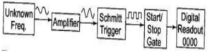
These pulses are fed to a start/stop gate. When the gate opens, pulses pass to the counter. When the gate closes, the counter stops. The number of pulses counted during the gate interval represents the frequency of the input signal.
Digital Frequency Meter Working Principle
The incoming signal is converted into trigger pulses and applied continuously to an AND gate. A precise 1-second pulse is applied to the other terminal of the AND gate. The number of pulses counted in this 1-second interval represents the frequency of the input signal.

Since each pulse corresponds to one cycle of the unknown signal, the count obtained directly indicates the frequency. High-speed electronic counters allow accurate measurement of even high-frequency signals.
Formula:
F = N / t
Where:
- F = Unknown frequency
- N = Number of counts
- t = Time interval between start and stop signals
Advantages
- Excellent frequency response
- High sensitivity
- Low production cost
Disadvantages
- Does not always provide an exact value due to limitations in timing accuracy
Applications
- Radio equipment testing
- Measurement of temperature, pressure, and other physical variables (using transducers)
- Vibration and strain measurements
- General purpose frequency measurement in laboratories and instrumentation systems